
Filtering antenna for wearable apparatus

a filtering antenna and wearable technology, applied in the direction of antenna earthing, substantially flat resonant elements, resonant antennas, etc., can solve the problems of low integration, low integration, and other shortcomings, and most of the currently designed wearable antenna technology does not have filtering function, etc., to achieve low profile, easy integration, and small size

Pending Publication Date: 2021-09-02
SOUTH CHINA UNIV OF TECH
View PDF0 Cites 1 Cited by
  • Summary
  • Abstract
  • Description
  • Claims
  • Application Information

AI Technical Summary

Benefits of technology

The present invention is a small-sized, easy-to-integrate, and high-gain filtering antenna that can be used in wearable devices. It has symmetrical rectangular slots on the surface of a circular patch, which generate a transmission null at a certain frequency point, resulting in a notch on the gain curve at that point. The position of the transmission null can be adjusted by changing the length of the rectangular slots. A second transmission null is generated at upper frequencies through the coupling of the feed network and the radiating patch. The antenna's overall thickness is reduced using an artificial magnetic conductor structure, improving its performance and reducing the impact of the human body's complex electromagnetic characteristics. The coupling feed structure also effectively increases the bandwidth of the microstrip antenna.

Problems solved by technology

On the other hand, most of the currently designed wearable antenna technologies have no filtering function.
Instead, a filter and an antenna are connected through a coaxial line to achieve filtering characteristics, which exhibits high loss, large volume, low integration and other shortcomings, which are not conducive to the development of the miniaturization of wearable devices.

Method used


Image

  • Filtering antenna for wearable apparatus
  • Filtering antenna for wearable apparatus
  • Filtering antenna for wearable apparatus

Examples


Embodiment Construction

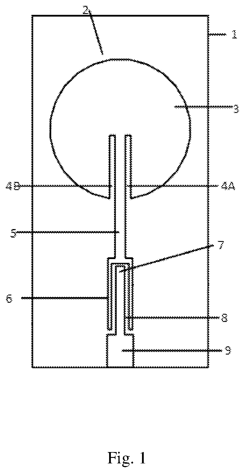
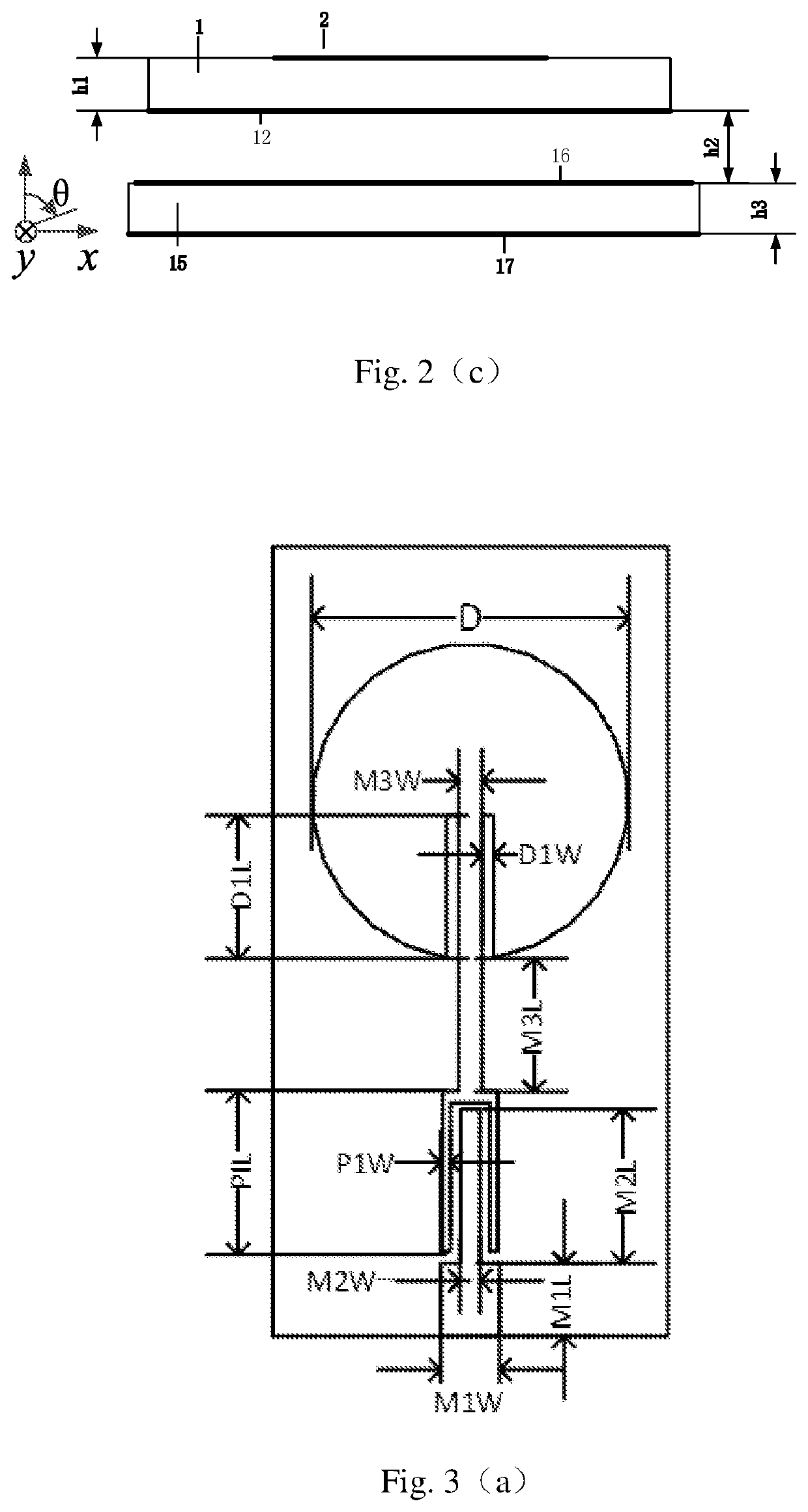
[0029]As shown in FIG. 1, FIG. 2(a), FIG. 2(b) and FIG. 2(c), a filtering antenna for wearable devices comprises a top dielectric substrate 1, a bottom dielectric substrate 15, an antenna radiation unit 2, a top metal ground 12, the bottom metal ground 17 and an artificial magnetic conductor structure. the antenna radiation unit is printed on an upper surface of the top dielectric substrate, the top metal ground is printed on a lower surface of the top dielectric substrate, the artificial magnetic conductor structure is etched on an upper surface of the bottom dielectric substrate, and the bottom metal ground is printed on a lower surface of the bottom dielectric substrate.

[0030]The antenna radiating unit is formed by a circular patch 3 and a microstrip coupling feed stub structure. The circular patch has two slots 4A, 4B, and the two slots are located in a lower part of the circular patch, extending from the circumference to the circle center. The two slots are parallel and symmetr...


PUM

PropertyMeasurementUnit
distanceaaaaaaaaaa
distanceaaaaaaaaaa
widthaaaaaaaaaa

Abstract

The invention discloses a filtering antenna for wearable devices, which includes a top dielectric substrate, a bottom dielectric substrate, an antenna radiation unit, a top metal ground, a bottom metal ground, and an artificial magnetic conductor structure. The antenna radiation unit is printed on an upper surface of the top dielectric substrate, the top metal ground is printed on a lower surface of the top dielectric substrate, the artificial magnetic conductor structure is etched on an upper surface of the bottom dielectric substrate, and the bottom metal ground is printed on a lower surface of the bottom dielectric substrate. The antenna radiation unit is formed by a circular patch and a microstrip coupling feed stub structure. The invention has the advantages of miniaturization, easy integration, low profile, high gain, anti-interference, may work in the 5.8-GHz ISM frequency band, may be used in wearable devices, has filtering effect etc., and is suitable in the field of human body wireless local area network communications.

Description

TECHNICAL FIELD[0001]The proposed invention relates to the field of wearable devices, in particular to a filtering antenna for wearable devices.TECHNICAL BACKGROUND[0002]As an important part of the fourth-generation wireless communication systems, human-centered communication can be applied in some specific situations, such as telemedicine, fire rescue, military battlefields, personal entertainment. Wearable antennas take critical role in the research of human-centered communication systems. Wearable antennas can be worn on the human body and can be integrated into smart devices on clothing or worn on a certain part of the human body, developed on the basis of conventional antennas. Different structures, materials and processes are introduced in the production process.[0003]Since the wearable antenna works in proximity of the human body, and the human body is formed by a variety of tissues with different shapes, different electromagnetic characteristics, and inhomogeneous dispersion...

Claims


Application Information

Patent Timeline
Patent Type & Authority Applications(United States)
IPC IPC(8): H01Q1/27H01Q1/52H01Q15/00H01Q9/04H01Q1/38
CPCH01Q1/273H01Q1/52H01Q1/38H01Q9/0407H01Q15/0006H01Q1/48H01Q1/50H01Q15/006H01Q9/045
Inventor LIU, XIONGYINGZHU, HAIXIANGLI, ZHONGXINYANG, HONGCAI
Owner SOUTH CHINA UNIV OF TECH
Learn More