
Inverter and over current protection method thereof

a protection method and converter technology, applied in the field of power conversion techniques, can solve the problems of ineffective over current protection, high latency and high loss of the hall sensor, and the enabling of the over current protection mechanism,

Active Publication Date: 2016-09-27
FSP POWERLAND TECH +1
View PDF8 Cites 1 Cited by
  • Summary
  • Abstract
  • Description
  • Claims
  • Application Information

AI Technical Summary

Benefits of technology

The invention provides an inverter that can quickly detect and protect against over current events. The inverter uses a filtering capacitor to detect current changes and determine if the inverter needs to enable its over current protection mechanism. This allows the inverter to quickly restrain the current and prevent damage to the system. The invention is not affected by delays in the hardware or software of the inverter, ensuring stability in power conversion.

Problems solved by technology

Nevertheless, the Hall sensor has defects of high latency and high loss, which leads the over current protection circuit incapable of enabling the over current protection mechanism immediately when the over current occurs in the inverter.
Accordingly, the conventional over current protection circuit can not effectively perform over current protection to improve the aforementioned situation.
When the sampled current signal is less than the reference value, the current limiting unit does not enable the over current protection mechanism according to the over current determination signal, such that the inverting circuit is normally operated.

Method used


Image

  • Inverter and over current protection method thereof
  • Inverter and over current protection method thereof
  • Inverter and over current protection method thereof

Examples


Embodiment Construction

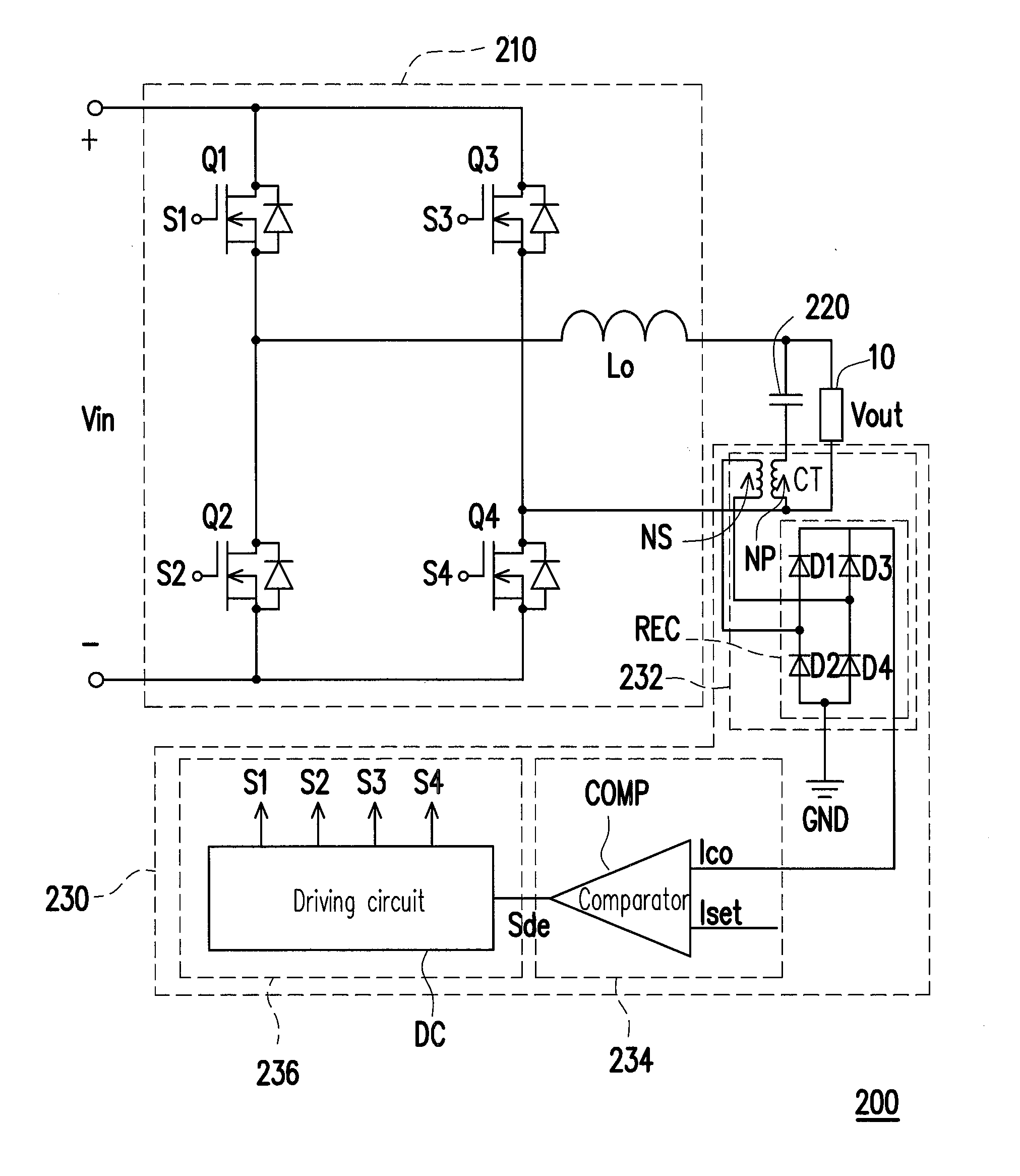
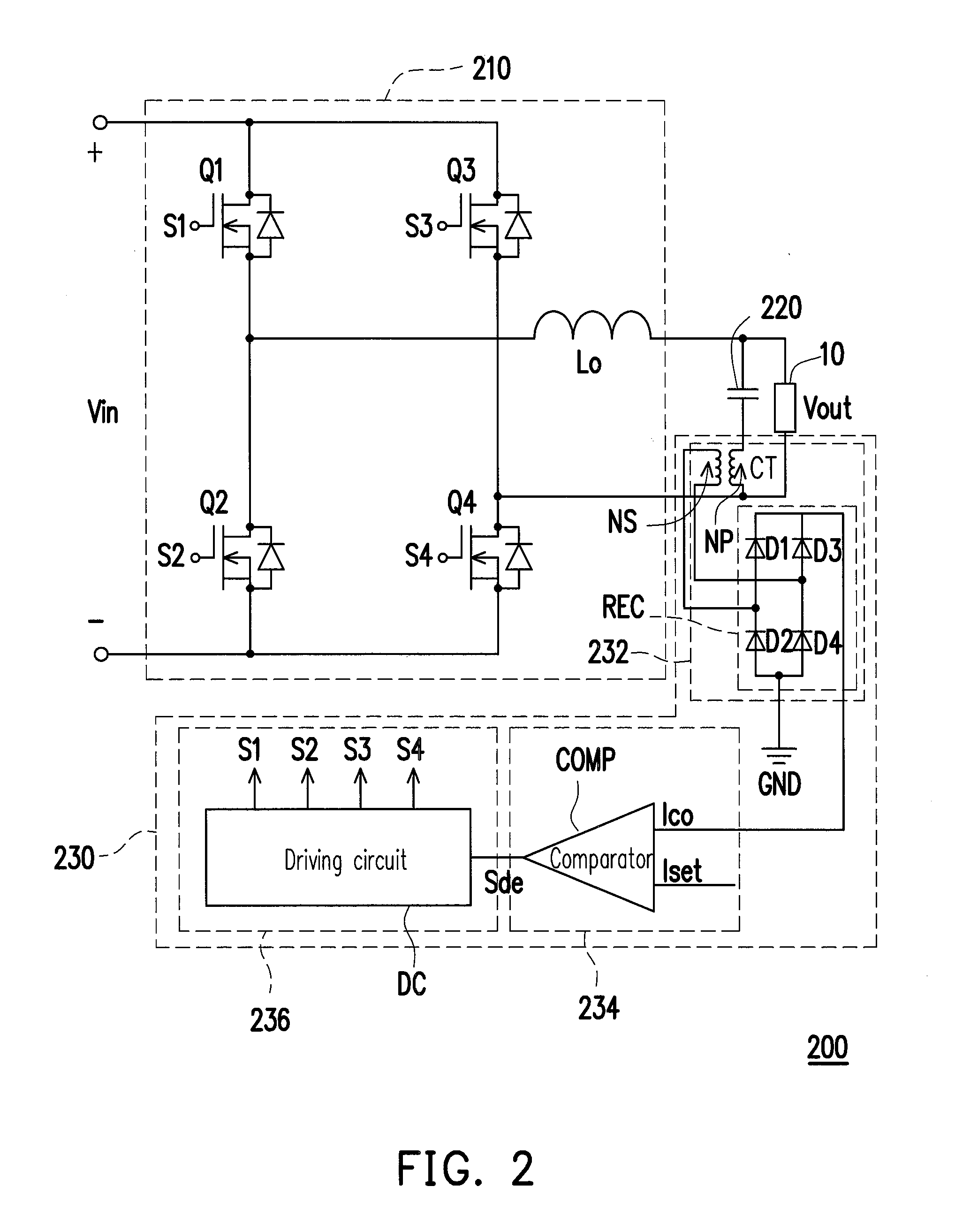
[0025]The invention provides an inverter and an over current protection method thereof. The inverter may detect an AC current of a filtering capacitor so as to determine whether to enable an over current protection mechanism accordingly. Accordingly, the inverter of the invention is capable of performing an over current protection quickly when an over current occurs, such that stability of the power conversion operation of the inverter can be enhanced. In order to make the disclosure of the invention more comprehensible, embodiments are described below as examples showing that the disclosure can actually be realized. Wherever possible, the same reference numbers are used in the drawings and the description to refer to the same or like parts.

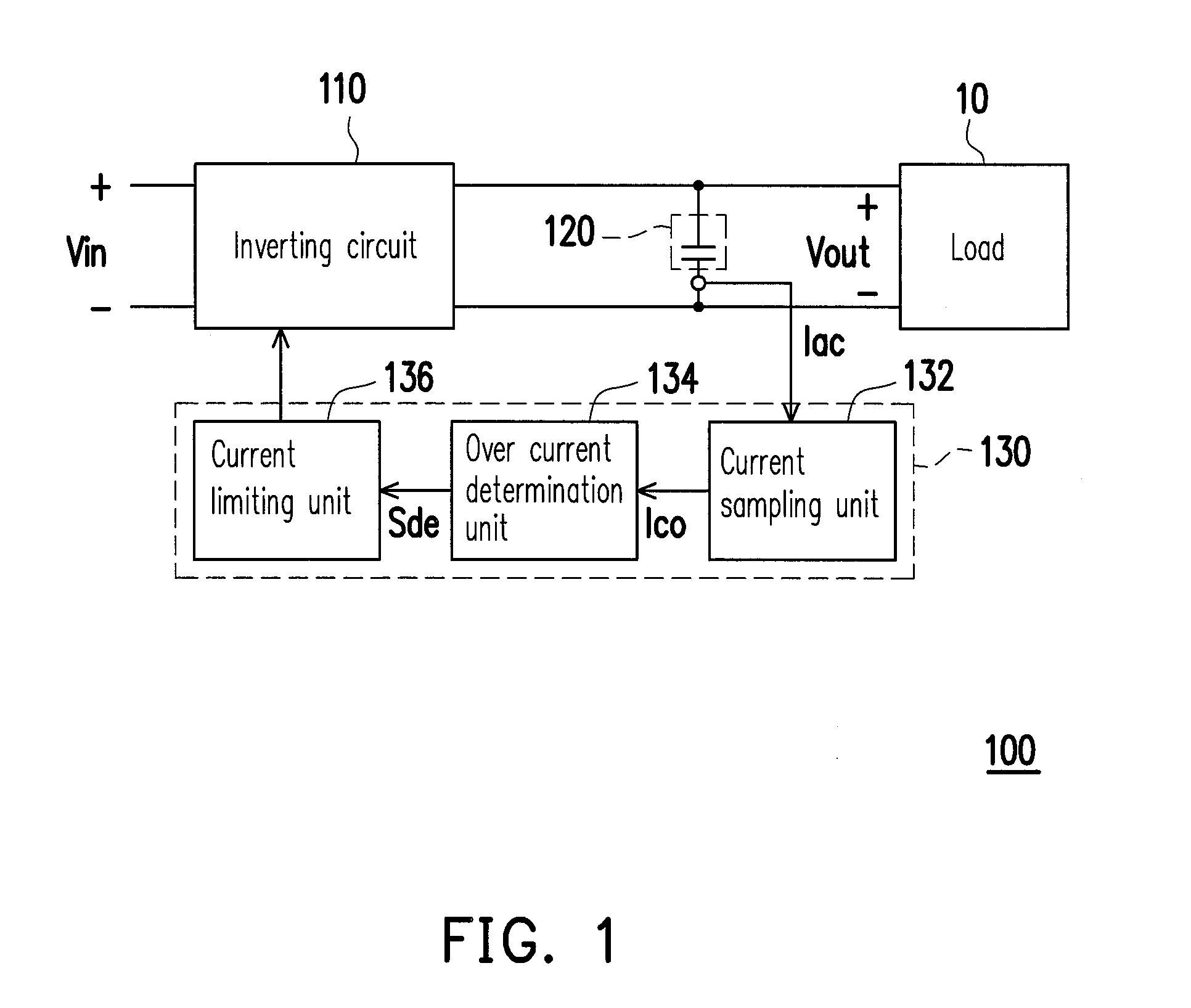
[0026]FIG. 1 is a schematic diagram of an inverter according to an embodiment of the invention. With reference to FIG. 1, an inverter 100 includes an inverting circuit 110, a filtering capacitor 120 and an over current protection circuit 130. An ...


PUM


Abstract

An inverter and an over current protection method thereof are provided. The inverter includes an inverting circuit, a filtering capacitor and an over current protection circuit. The inverting circuit is configured to convert a DC input voltage into an AC output voltage and provide the AC output voltage to a load. The filtering capacitor is coupled to the inverting circuit and the load in parallel. The over current protection circuit is coupled to the inverting circuit and the filtering capacitor and configured to provide an over current protection mechanism. The over current protection circuit detects an AC current on the filtering capacitor and determines whether to enable the over current protection mechanism according to the AC current in order to restrain the power conversion operation of the inverting circuit.

Description

CROSS-REFERENCE TO RELATED APPLICATION[0001]This application claims the priority benefit of China application serial no. 201310331139.X, filed on Aug. 1, 2013. The entirety of the above-mentioned patent application is hereby incorporated by reference herein and made a part of this specification.BACKGROUND[0002]1. Field of the Invention[0003]The invention is directed to a power conversion technique and more particularly to an inverter and an over current protection method thereof.[0004]2. Description of Related Art[0005]In order to protect the operational stability of the entire circuit, a designer of an inverter generally adds an over current protection circuit into the inverter. In this way, a corresponding over current protection mechanism will be enabled to protect the entire circuit form being damaged when a large current flows through a circuit of the inverter.[0006]The prior art of the over current protection circuit typically performs a current sampling operation at an output...

Claims


Application Information

Patent Timeline
Patent Type & Authority Patents(United States)
IPC IPC(8): H02M1/32H02M7/5387H02M1/00
CPCH02M1/32H02M7/5387H02M2001/0009H02M1/325H02M1/0009
Inventor WANG, CHUAN-YUNXU, MINGMU, JIAN-GUO
Owner FSP POWERLAND TECH
Learn More