Container for the generation of therapeutic microfoam

a technology of microfoam and container, which is applied in the field of container for the generation of therapeutic microfoam, can solve the problems of ineffective concentration of sclerosant at the concentration required to limit the dosage to safe levels, the inapplicability of the inability to apply sclerotherapy to large varicose veins. , to achieve the effect of diffusion through the alveolar

Inactive Publication Date: 2016-10-04
BTG INT LTD
View PDF76 Cites 2 Cited by
  • Summary
  • Abstract
  • Description
  • Claims
  • Application Information

AI Technical Summary

Benefits of technology

[0046]The sclerosant liquid may be stored at atmospheric pressure (or just above) before the blood-dispersible gas is introduced. The sclerosant liquid may be stored in the presence of an inert gas or mixture of inert gases. “Inert gas”, as used in this specification, refers to one which is unlikely to react with the sclerosant liquid so as to change its chemical nature. Suitable inert gases include carbon dioxide, helium, neon, argon, and nitrogen. Carbon dioxide is most preferred, as it is physiologically acceptable, as part of the final gas mix in the microfoam. Helium is next best, as it is of small molecular weight, and diffuses through alveolar blood vessel walls very quickly.
[0047]Advantageously, a vacuum can be drawn on the expandable inner container prior to or after filling with sclerosant. This reduces to a minimum the amount of gas, particularly undesirable gases, such as nitrogen or carbon dioxide, which may affect the sclerosant during storage or the composition of the resulting f

Problems solved by technology

Sclerotherapy and surgery complemented one another but treatment by sclerotherapy continued to be inapplicable to large varicose veins.
In these large varicose veins, if a sclerosing liquid was injected, the amount of liquid sclerosant required to fill the entire length of the varicose vein exceeded safe dosage limits at normal sclerosant concentrations, and may be ineffective at the concentrations required to limit the dosage to safe levels.
However, this known method requires extemporaneous production of microfoam by the physician, pharmacist or an assistant immediately prior to administration to the patient.
This is particularly an issue where large vessels are being filled with foam, if air is used as the gas for producing the foam.
However, the present inventors have identified a potential problem with this formulation, in making the observation that polidocanol, when stored for several months in the presence of oxygen, may slowly decompose.
Thus

Method used


Image

  • Container for the generation of therapeutic microfoam
  • Container for the generation of therapeutic microfoam
  • Container for the generation of therapeutic microfoam

Examples


example 1

“Bag-in-can” Device

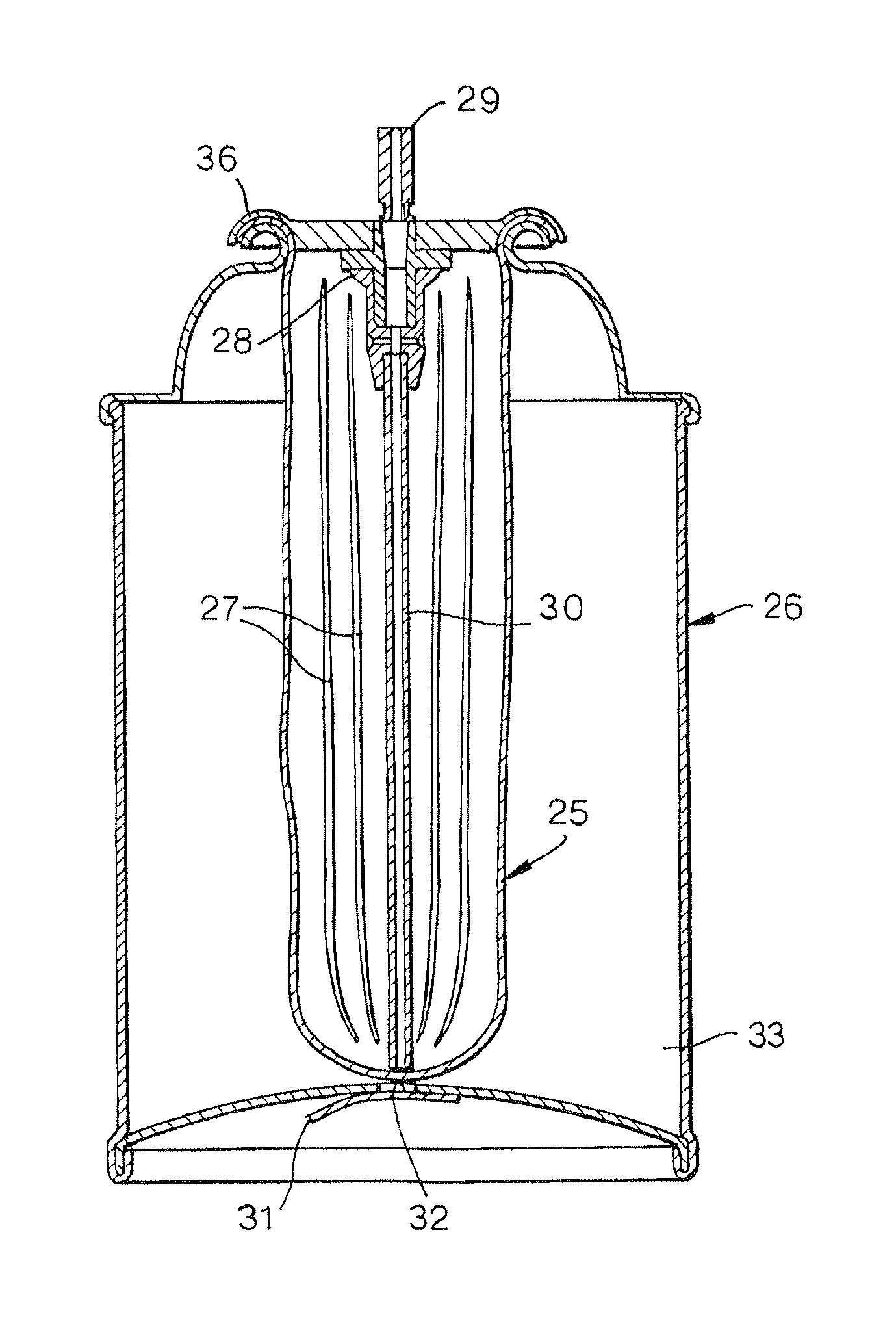
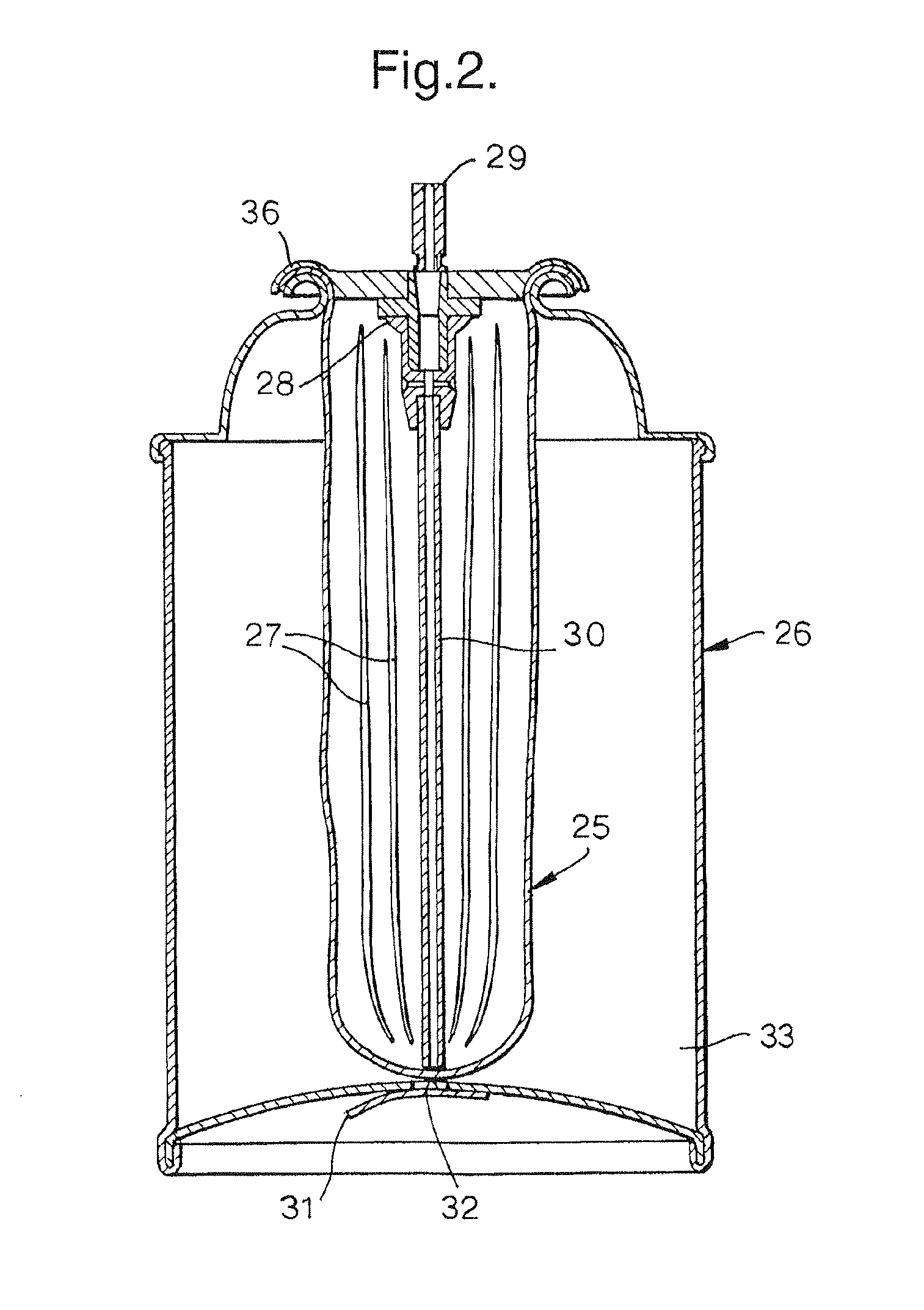
[0079]A first embodiment of the present invention is shown in FIG. 2. The device uses a standard bag-in-can construction of the type supplied by US Can Corporation of Lombard, Ill., or Crown Cork & Seal Company Inc. of Philadelphia, Pa. The bag (25), typically composed of blow moulded nylon 6,6 or HDPE, but not limited to these polymers, and of an inflated size ideally equal to or greater than the internal volume of the canister, is inserted into the can (26) through the open mouth of the canister. A number of axial pleats (27) in the bag wall (25) aid in easy insertion of the bag through the open mouth of the can. A mixing valve (28) (e.g. Ecosol™ type, Precision Valve, Peterborough, UK) is crimped onto the can, trapping the mouth of the bag in the valve crimp (36) and effecting a seal.

[0080]A vacuum pump is attached to the stem valve outlet (29) of the sealed can, the valve is depressed to open a pathway to the bag interior, and a vacuum drawn inside the bag to ...

example 2

“Bag-on-Valve” Device

[0084]A further embodiment of the present invention is shown in FIG. 4, which is broadly similar in operation to Example 1, though incorporating a “bag-on-valve” device. FIG. 4 shows the device in its unfilled state. Such bags are normally constructed from a tri-layer laminate comprising a heat sealable material on the inner surface (PVdC or similar), an aluminium foil as the centre layer, and a tough plastic for the outer layer (PET, Nylon 6,6 or similar). The bags are normally supplied coiled or furled around the central long axis by companies such as Coster Aerosols Ltd., Stevenage, UK, and normally contain a dip tube (30). To keep them tightly furled, it is normal practice to employ a number of adhesive tape tabs (34) that are based on a weak paper backing. When the bag (25) is subsequently inflated, these tabs tear and allow the bag to fill almost the entire volume of the canister (26). In this example, it is critical that the weld between the bag and the v...

example 3

Container with Engaging Means and Mesh Stack Shuttle

[0086]A device comprising a container provided with engaging means and a mesh stack shuttle according to the invention, as disclosed in the co-pending application WO 02 / 41872-A1, is shown in FIG. 6. The device comprises a container (1) for an aqueous sclerosant liquid, a container (2) for a physiologically acceptable blood-dispersible gas and an engaging means comprising a connector (3).

[0087]The container (1) for the aqueous sclerosant liquid is pressurised to a level of 0.5 bar absolute. The container (2) for a physiologically acceptable blood-dispersible gas is charged with pure oxygen gas at 5.8 bar absolute pressure. Container (2) is used to pressurise the container (1) for the aqueous sclerosant liquid just before the microfoam is required, and is then discarded. The two containers will thus be referred to hereinafter as the PD [polidocanol] can (1) and the O2 can (2). In this example each of the containers (1,2) has approxim...


PUM

PropertyMeasurementUnit
Lengthaaaaaaaaaa
Lengthaaaaaaaaaa
Densityaaaaaaaaaa

Abstract

Device containing sclerosant liquid for use in the treatment of blood vessels having an aerosol valve housing containing gas-entry ports. The aerosol valve housing is mounted on a canister having an expandable inner container in which the sclerosant fluid is contained. The expandable inner container is affixed to the outer opening of the canister or to the aerosol valve housing above the valve gas-entry ports so that gas taken from the interior of the expandable inner container can mix with the sclerosant liquid to create a micro foam, such that introduction of pressurized gas through the aerosol valve causes the expandable inner container to inflate to accommodate the pressurized gas.

Description

[0001]This application is a continuation of application Ser. No. 13 / 862,083 filed Apr. 12, 2013, abandoned, which is a continuation of application Ser. No. 10 / 513,911, filed Dec. 23, 2004, abandoned, which is a 371 of PCT / GB03 / 02226, filed May 23, 2003, which claims priority to British Patent Application No. 0212047.5 filed May 24, 2002, the entire contents of each of which are hereby incorporated by reference.[0002]The present invention relates to a method and apparatus for the generation of foam comprising a sclerosing material, particularly a sclerosing liquid, which is suitable for use in the treatment of various medical conditions involving blood vessels, particularly varicose veins and other disorders involving venous malformation.BACKGROUND OF THE INVENTION[0003]Sclerosis of varicose veins is based on the injection into the veins of liquid sclerosant substances which, by inter alia causing a localised inflammatory reaction, favour the elimination of these abnormal veins. Unti...

Claims


Application Information

Patent Timeline
IPC IPC(8): A61M11/00B65D83/62A61M11/02B65D83/42A61K9/12B65D83/14
CPCA61M11/00A61K9/12A61K9/122A61M11/02B65D83/425B65D83/62A61M2202/03A61M2205/3344
Inventor WRIGHT, DAVID DAKIN IORWERTHHARMAN, ANTHONY DAVID
Owner BTG INT LTD
Why Eureka
Try Eureka