Waterproof control unit

a control unit and water-proof technology, applied in the direction of electrical apparatus, electrical apparatus, electrical apparatus contruction details, etc., can solve the problems of increasing the dimension of the plurality of contact terminals, the need for increasing the apparent thickness dimension between the sealing faces, and the long-bodied of the connection housing

Active Publication Date: 2016-10-04
MITSUBISHI ELECTRIC CORP
View PDF15 Cites 15 Cited by
  • Summary
  • Abstract
  • Description
  • Claims
  • Application Information

AI Technical Summary

Benefits of technology

[0030]Accordingly, the invention provides an effect of simplifying the mold structure for the cover or the base to be mold-processed or sheet metal-processed, thereby reducing the mold cost and also configuring the connector housing so as not to be long bodied, thereby allowing use of an inexpensive connector pin.
[0031]Furthermore, in comparison with providing two set of convexo-concave seal faces (one set for the cover, the other set for the base) on the connector housing, for example, using terrace slope portions for the cover and the base or combining terrace slope portions and one set of convexo-concave seal faces is possible, this combination providing an effect of reducing the total width of the seal faces and achieving sealing performance not inferior to the case using two set of convexo-concave seal faces.
[0032]Note that, even in combining terrace slope portions and one set of convexo-concave seal faces, the mold structure can be simplified by increasing the width of the convexo-concave seal faces and decreasing the fitting depth with respect to the case of providing two set of convexo-concave seal faces.
[0033]Furthermore, advantageously, terrace slope portions allow the seal path to be longer than that of horizontal planes and can improve strength of the thin-walled cover or base and reduce the thickness and cost of the cover or base.

Problems solved by technology

On the other hand, a first disadvantage of the convexo-concave seal face method is that, as described above, two types of convexo-concave seal faces need to be provided in the connector housing, which causes the connector housing to be long-bodied and also increases the dimension of the plurality of contact terminals press-fit into the connector housing, so a measure to suppress increase in the electric resistance is required.
Furthermore, a second disadvantage of the convexo-concave seal face method is that, in order to ensure an adequate fitting depth of the convexo-concave faces, the apparent thickness dimension between the seal faces needs to be increased.
Furthermore, a third disadvantage is that, for example, with a sheet metal cover, it is difficult to make a fine convexo-concave face that is narrow and deep, and even with a resin-molded cover, it is almost impossible to make a convexo-concave face that is excessively narrow and deep from the viewpoint of mold life, so an expected compact size is limited, and an attempt to reduce the load on the mold increases the body length of the connector housing.
However, the two types of convexo-concave seal faces provided on the connector housing 41 are placed deviated from each other, which causes the connector housing to be long-bodied.
Accordingly, the connector opening portion of the upper case 20 and the connector opening portion of the lower case 30 are rising up to the middle portion of the side face of the connector, so a problem is that the total weight is large when, for example, the lower case 30 is made of aluminum die-cast and the upper case 20 is resin-molded.
Accordingly, the lower case 70 is extended beyond the partition wall of the housing 111, so a problem is that the total weight is large when, for example, the lower case 70 is made of aluminum die-cast and the upper case 50 is resin-molded.
Accordingly, a problem is that a long-bodied connector is provided.
Another problem is that the cover 20 and the base 30 are made of a sheet metal, and the convexo-concave seal face pressed corrugated is shallow and wide, so the connector is further long-bodied and the connector pin is elongated, which increases the cost.
Another problem is that, even when the cover is resin-molded and the base is made of aluminum die-cast, for a narrow and deep convexo-concave seal face, making a mold is difficult, demolding is difficult, and also mold life is short.

Method used


Image

  • Waterproof control unit
  • Waterproof control unit
  • Waterproof control unit

Examples


first embodiment

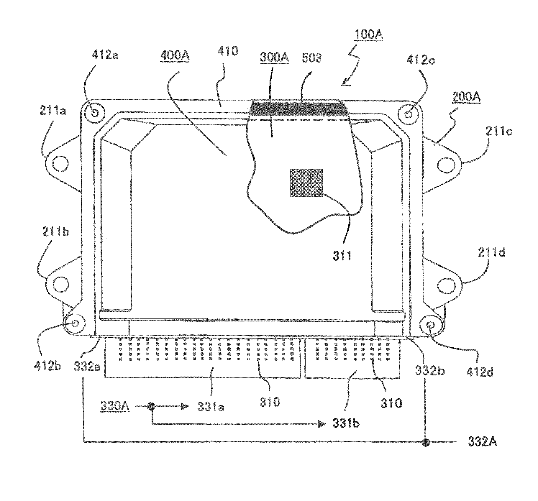
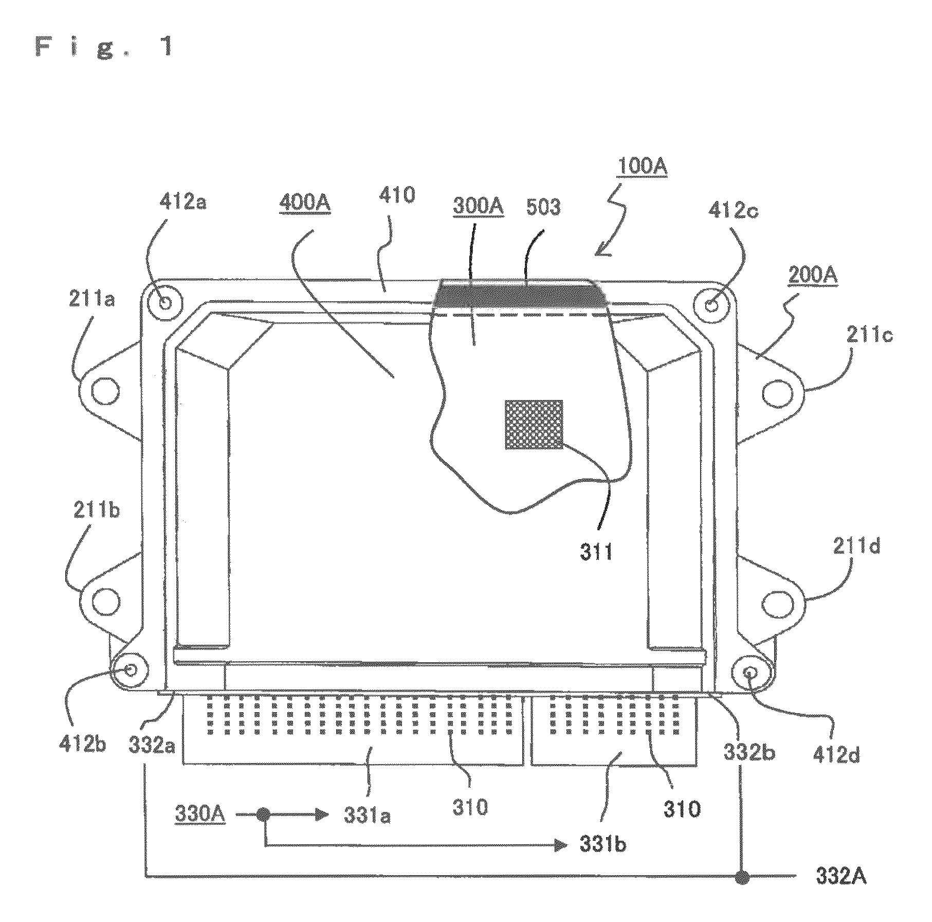
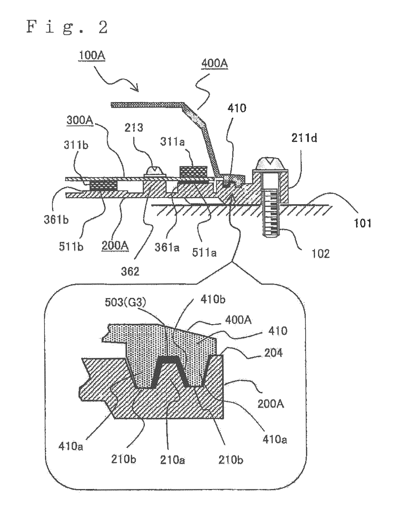
[0049]First, a waterproof control unit in accordance with a first embodiment of the invention is described with reference to FIGS. 1 to 7. In FIG. 1, a waterproof control unit 100A includes: an aluminum die-cast base 200A having mounting legs 211a-211d at four locations; a circuit board 300A with a plurality of circuit components 311 and heat-generating components 311a, 311b described later (see FIG. 2) mounted thereon; and a bottomless box-shaped resin cover 400A having a flange 410 on the outer periphery wall at three of the sides, in which, on the other one side of the cover 400A, corresponding part of the outer periphery wall is missing and a side face opening 100W (see FIG. 3) closed by a connector housing 330A is provided.

[0050]Note that an enclosure of the waterproof control unit 100A is formed of the base 200A and the bottomless box-shaped resin cover 400A covering the base 200A. A first and second connector housings 331a, 331b are integrally molded into the connector housin...

second embodiment

[0113]A waterproof control unit in accordance with a second embodiment of the invention is described below with reference to FIGS. 8 to 13.

[0114]In FIG. 8, a waterproof control unit 100B includes: a sheet-metal base 200B having mounting legs 211B, 211B on the right and left sides; a circuit board 300B with circuit components 311 and heat-generating components 311a, 311b described later mounted thereon; and a sheet-metal cover 400B having a flange on the outer periphery wall at three of the sides, in which, on the other one side of the cover 400B, corresponding part of the outer periphery wall includes, in part, a side face opening 100W closed by a connector housing 330B. The circuit board 300B is held between the cover 400B and the base 200B, and the cover 400B and the base 200B are integrated with each other by folding and pressurizing / tightening (fixedly swaging) folding pieces 413 provided at the four corners of the cover 400B.

[0115]The connector housing 330B is attached to one s...


PUM


Abstract

A waterproof control unit is provided in which: connector housing is fixedly positioned onto circuit board that is mounted onto base; a first seal gap G1 formed of the connector housing and a cover, a second seal gap G2 formed of the connector housing and the base and a third seal gap G3 formed of the base and the cover are included; the first seal gap G1 is formed of a terrace slope portion gap G1b and an outer step flat portion gap G1a and an inner step flat portion gap G1c that are in communication with the terrace slope portion gap G1b; a gap setting protrusion for limiting the gap width is provided at least in the first seal gap G1; and, between the connector housing and the cover, a horizontal movement limitation member are provided for limiting the relative positional relationship between the connector housing and the cover.

Description

BACKGROUND OF THE INVENTION[0001]1. Field of the Invention[0002]The present invention relates to a waterproof control unit, such as an in-vehicle electronic control unit installed in an engine room.[0003]2. Description of the Related Art[0004]Among conventional waterproof control units, one example waterproof control unit that is widely used includes: an enclosure formed of a base and a cover as described below; a circuit board hermetically contained in the enclosure with circuit components and a plurality of contact terminals for external connection mounted thereon and a resin-molded connector housing positioned and fixed; and waterproof seal material that fills first to third seal gaps in order to expose outside the enclosure the edge face of the connector housing with the plurality of contact terminals provided therethrough, the first seal gap being provided between the abutting faces of the connector housing and the cover, the second seal gap being provided between the abutting ...

Claims


Application Information

Patent Timeline
Patent Type & Authority Patents(United States)
IPC IPC(8): H05K7/00H05K5/00H05K5/06
CPCH05K5/061H05K5/0056H05K5/06
Inventor NURIYA, NOBUAKINISHIDA, MITSUNORINISHIZAWA, OSAMU
Owner MITSUBISHI ELECTRIC CORP
Why Eureka
Try Eureka