Cavity acoustic tones suppression

a technology of acoustic tones and cavity walls, applied in the direction of boundary layer controls, influencers by generating vortices, sound producing devices, etc., can solve the problems of characteristic rate of acoustic noise generation and noise emission, and achieve the effect of increasing the thickness of the shear layer

Active Publication Date: 2016-10-11
BAE SYSTEMS PLC
View PDF18 Cites 3 Cited by
  • Summary
  • Abstract
  • Description
  • Claims
  • Application Information

AI Technical Summary

Benefits of technology

[0007]The present inventor has realised that it would be desirable to provide a form of suppression by generating multiple fine scale turbulances i.e. resulting in multiple small vortices, within the shear layer, thereby disrupting the formation of large scale vortices in the shear layer which are part of the tone generation process, and moreover to provide that the multiple fine scale turbulances tend not to combine into larger ones. The present inventor has further realised that one way, for example, to deter the combination of the fine scale turbulence into larger ones would be to increase the thickness of the shear layer formed at the cavity (note for example, that in contrast the prior art arrangements disclosed in the above mentioned prior art documents do not have a tendency to thicken the shear layer). The present inventor has realised that, conventionally, an upstream acoustic wave interacts with the vortices in the shear layer at approximately common times i.e. they display a temporal coherence. The present inventor has realised that in contrast, by providing a thicker shear layer, the vortices closer to the stream flow will propagate downstream faster than those closer to the static air in the bay. The present inventor has realised that therefore at some point downstream the vortices will arrive at different times to each other. The present inventor has realised that this loss of temporal coherence will disrupt the formation of the conventional large scale turbulent structures that would otherwise play a key role in the generation of unwanted acoustic tones. The present inventor has further realised it is advantageous in itself to provide features of a suppression system inside the cavity rather than outside. For example, the inventor has realised that for closable cavities this would allow the features to be easily removed from the e.g. aircraft's airflow when the cavity is closed.
[0025]The effect of the rods may be to increase the thickness of the shear layer.

Problems solved by technology

A vortex is shed from the cavity leading edge and grows as it travels down the shear layer and impacts on the aft (trailing) wall of the bay resulting in the emission of noise.
This results in acoustic noise being generated at a characteristic rate which may be described as acoustic tones of a characteristic frequency.

Method used


Image

  • Cavity acoustic tones suppression
  • Cavity acoustic tones suppression
  • Cavity acoustic tones suppression

Examples


Embodiment Construction

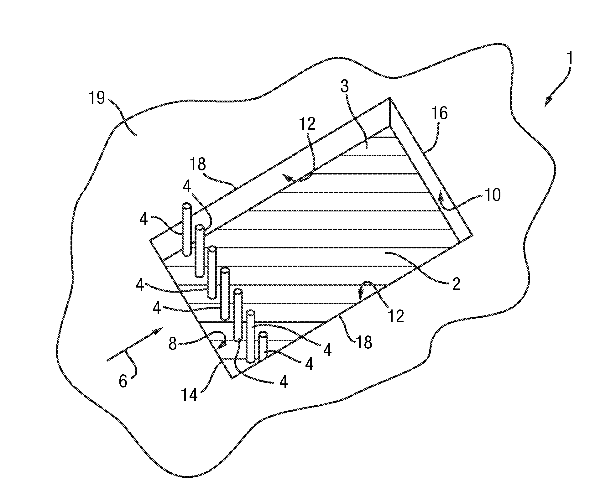
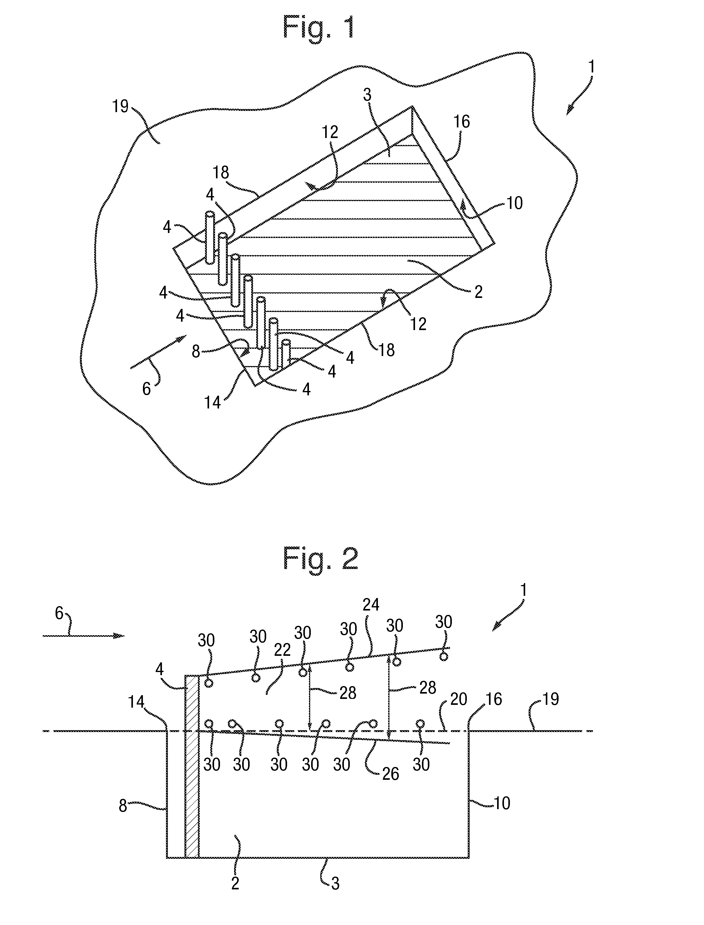
[0041]It will be appreciated that relative terms such as horizontal and vertical, top and bottom, above and below, front and back, and so on, are used above merely for ease of reference to the Figures, and these terms are not limiting as such, and any two differing directions or positions and so on may be implemented rather than truly horizontal and vertical, top and bottom, and so on. In particular, for convenience, in the Figures a cavity is shown with it opening at the top of the page, and so for convenience the word “top” is used to mean the opening of the cavity, and the word “above” means further away from the cavity, However, it will be appreciated that the present invention refer also to cavities positioned for example underneath the wing or fuselage of e.g. an aircraft, i.e. upside down to that shown in the Figures, but the description use of the word “top” will still refer to the opening part of the cavity and that of the word “above” will still refer to being away from th...


PUM


Abstract

A cavity system that tends to increase the thickness (28) of the shear layer (22), comprising: a cavity (2) and a plurality of rods (4) extending away from the cavity base (3) to a height extending beyond the leading edge (14); the rods (4) being positioned downstream of and in the proximity of the leading edge (14). The rods (4) may extend to different heights and / or be positioned longitudinally offset (e.g. in a zig-zag pattern). The rods may be reversibly movable to a configuration in which they are fully enclosed in the cavity (2) when the cavity (2) is closed. Flow alteration elements (34, 38), for example channels (34) passing through the rods (4) and / or protrusions (38) extending from the rod (4) may be provided on the rods (4).

Description

RELATED APPLICATIONS[0001]This application is a national phase application filed under 35 USC §371 of PCT Application No. PCT / GB2014 / 050758 with an International filing date of 13 Mar. 2014 which claims priority of GB Patent Application 1304716.2 filed 15 Mar. 2013 and EP Patent Application 13275064.7 filed 15 Mar. 2013. Each of these applications is herein incorporated by reference in their entirety for all purposes.FIELD OF THE INVENTION[0002]The present invention relates to methods and systems for suppression of acoustic tones and / or resonance and / or other acoustic tone effects in cavities for when they are moving relative to an ambient fluid. The present invention relates in particular to, but is not limited to, such methods and systems for cavities recessed in a surface, for example in a surface of a vehicle, for example aircraft cavities, for example bays, when the aircraft is travelling through air.BACKGROUND[0003]Considering the case of a surface with a cavity recessed in th...

Claims


Application Information

Patent Timeline
Patent Type & Authority Patents(United States)
IPC IPC(8): B64C23/06B64D1/06B60R13/08B64C23/00G10K11/16
CPCB64C23/005B60R13/08G10K11/16B64C2230/08Y02T50/166Y02T50/10B64C21/00B64C23/06F15D1/12G10K11/161
Inventor PATIENCE, DAVID EUAN
Owner BAE SYSTEMS PLC
Why Eureka
Try Eureka