
Semi constrained polyaxial endoprosthetic ankle joint replacement implant

a polyaxial, ankle joint technology, applied in the field of orthopaedic prostheses and joint replacement systems, can solve the problems of limited and risky access to the ankle joint, the concept of total ankle arthroplasty has a long and relatively unsuccessful history, and the replacement of an ankle joint with an ankle prosthesis can be particularly challenging

Active Publication Date: 2016-10-18
PERLER ADAM D
View PDF1 Cites 3 Cited by
  • Summary
  • Abstract
  • Description
  • Claims
  • Application Information

AI Technical Summary

Benefits of technology

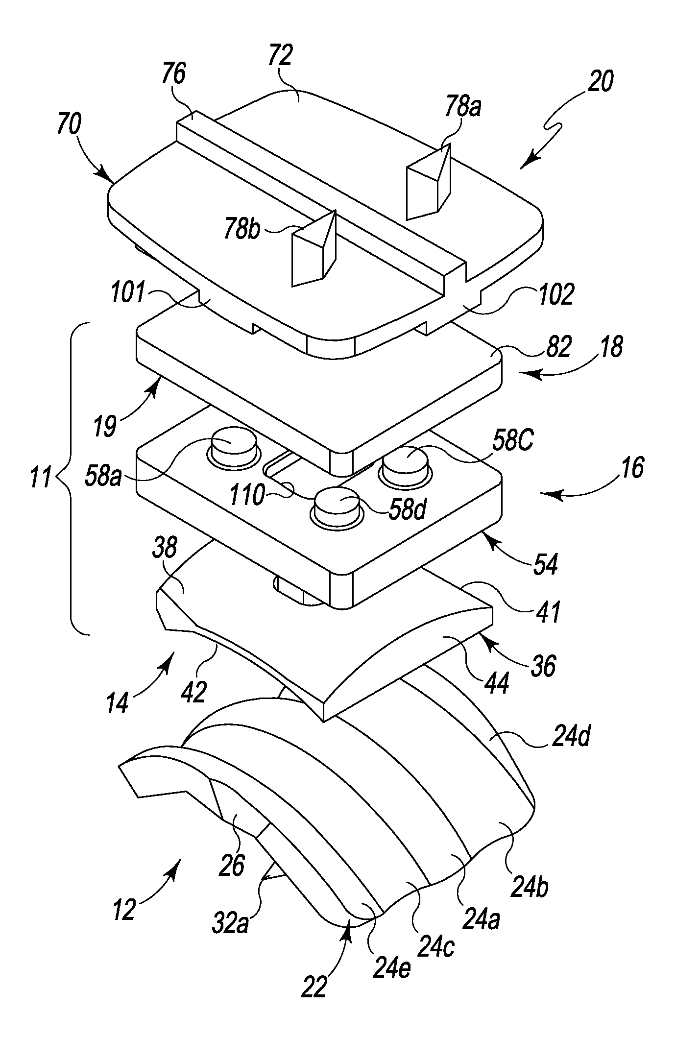
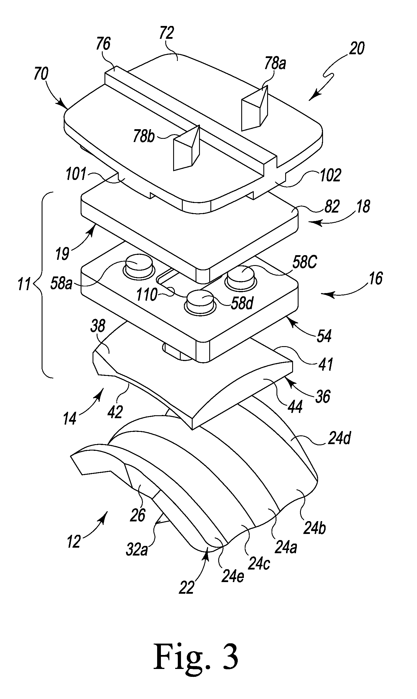
[0017]The polyaxial mobile bearing component has a smooth superior surface adapted for gliding on a smooth inferior surface of the tibial component to allow desired rotational and translational movements. The polyaxial mobile bearing component has a contoured inferior surface that is mostly congruent with a contoured superior surface of the talar component which allows for frontal plane motion, but limits the transverse and sagital plane motion. The inferior surface has a proximal surface that is mostly congruent with a distal aspect of the proximal bearing while the distal aspect of the inferior surface is mostly congruent with the superior surface of the talar component and allows for mostly sagittal plane rotation / motion / excursion.

Problems solved by technology

The concept of total ankle arthroplasty has a long and relatively unsuccessful history due to the high failure rate often associated with the original implant devices and implantation techniques.
It has been shown that replacement of an ankle joint with an ankle prosthesis can be particularly challenging due to the relatively small articular contact surfaces of the ankle, complex biomechanics of both the ankle and hindfoot joints, limited and risky access to the ankle joint during replacement, and wide variation in patient candidacy.
Past flawed design rationale and the above factors have led to a high rate of post-operative complications such as loosening of the ankle prosthesis, subsidence, pain, abnormal ankle prosthesis wear, and / or meniscal / bearing breakdown—often leading to ankle implantation failure.
In addition to the technical difficulties, regulatory agencies have classified ankle prosthetics in a manner which is often viewed as substantially limiting scientific progress in the field of ankle replacement due to the financial burden of obtaining market clearance for such devices.
Rotations in the frontal plane or motion in the transverse plane are usually not well supported as there is little curvature in this region.
These motions can occur actively and lead to edge loading, causing higher stress and greater propensity for wear.
Also, as the articular surfaces can be designed for mismatch, even under optimum implant positioning and loading, higher stress will be seen at the contact point due to the point loading associated with mismatched radii of the articular surfaces as the surface contact areas are smaller and thus experience much greater loads.
The current systems in this category do not often address the frontal plane motion influence of the underlying subtalar joint axis.

Method used


Image

  • Semi constrained polyaxial endoprosthetic ankle joint replacement implant
  • Semi constrained polyaxial endoprosthetic ankle joint replacement implant
  • Semi constrained polyaxial endoprosthetic ankle joint replacement implant

Examples


Embodiment Construction

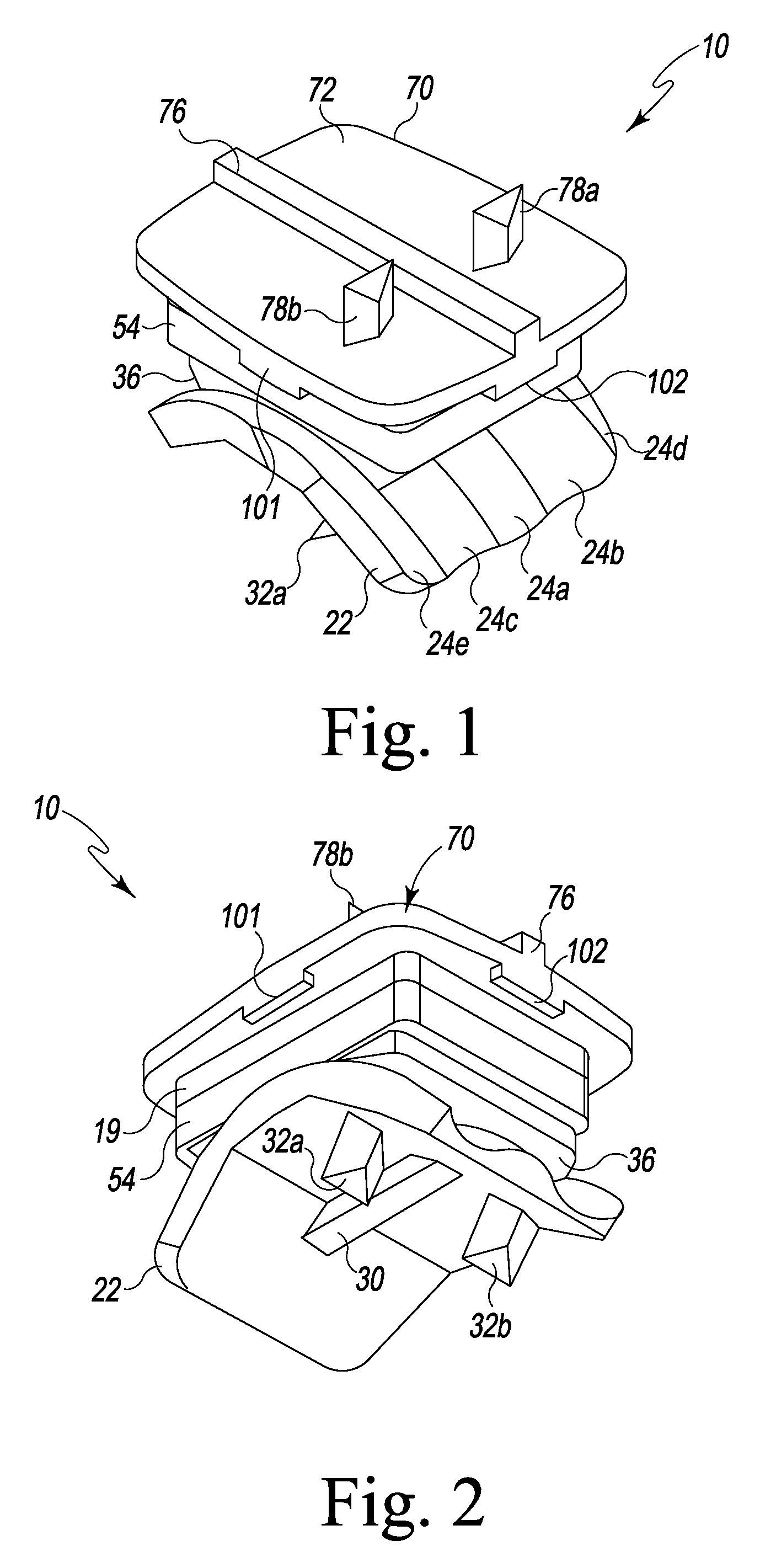
[0040]Referring to FIGS. 1-19, there is depicted a semi constrained polyaxial ankle joint replacement implant or prosthesis 10 fashioned in accordance with the present principles. The semi constrained polyaxial endoprosthetic ankle joint replacement implant 10 (i.e. ankle implant or prosthesis) has several components that interact to provide an ankle prosthesis which mimics a natural ankle joint (i.e. as between the tibia and the talus / calceneus). Particularly, the ankle prosthesis 10 includes a talus or talar (hereinafter collectively, talar) component or plate 12 that is configured for attachment to the talus or calceneus bone (not shown), a tibia or tibial (hereinafter collectively, tibial) component or plate 20 that is configured for attachment to the tibia bone (not shown), and a dual bearing component 11 situated between the talar plate 12 and the tibial plate 20 that is configured to allow articulation or translation with respect to the talar plate 12 and allow articulation o...


PUM


Abstract

A semi-constrained polyaxial ankle joint replacement implant has a dual bearing component, a tibial component or plate adapted for attachment to a tibia or fibula bone, and a talar component or plate adapted for attachment to a talus or calceneus bone of the foot. The dual bearing component includes a superior bearing providing gliding articulation / translation between it and the tibial component, and an inferior bearing providing gliding articulation / translation between it and the talar component. The tibial plate has peripheral transversely extending flanges that semi constrain or limit movement relative to the superior bearing and / or vice versa. The inferior bearing has a flange extending upwardly from the superior surface thereof that is received in an opening in the intermediate plate to semi constrain or limit movement relative between the two components.

Description

CROSS REFERENCE TO RELATED APPLICATIONS[0001]This non-provisional patent application claims the benefit of and / or priority under 35 U.S.C. §119 to U.S. Provisional Patent Application Ser. No. 61 / 863,394 filed Aug. 7, 2013, entitled “Polyaxial Endoprosthetic Ankle Joint Replacement Implant” the entire contents of which is specifically incorporated herein by this reference.[0002]This non-provisional patent application is also related to and specifically incorporates herein by reference U.S. patent application Ser. No. 13 / 286,760 filed Nov. 1, 2011, entitled “Prosthetic Device with Multi-Axis Dual Bearing Assembly and Methods for Resection.”BACKGROUND OF THE INVENTION[0003]1. Field of the Invention[0004]The present subject matter is directed generally to orthopedic prostheses, joint replacement systems and methods and, more particularly, to a multi-axis mobile bearing ankle prosthesis.[0005]2. Background Information[0006]The concept of total ankle arthroplasty has a long and relatively...

Claims


Application Information

Patent Timeline
Patent Type & Authority Patents(United States)
IPC IPC(8): A61F2/42A61F2/30
CPCA61F2/4202A61F2002/30227A61F2002/30354A61F2002/30604A61F2002/30845A61F2002/30848A61F2002/30884A61F2002/30892A61F2002/4205A61F2002/4207
Inventor PERLER, ADAM D.
Owner PERLER ADAM D
Learn More