Pump

a technology for pumps and pumps, applied in the field of pumps, can solve problems such as air interference with the efficiency of pumps

Active Publication Date: 2016-10-18
E G O ELEKTRO GERAETEBAU GMBH
View PDF19 Cites 2 Cited by
  • Summary
  • Abstract
  • Description
  • Claims
  • Application Information

AI Technical Summary

Benefits of technology

[0005]The object underlying the invention is to provide an abovementioned pump by means of which problems of the prior art can be solved, and in particular a pump can be provided that performs efficiently and most important that can discharge air present in the pump chamber during the start of the pumping procedure.
[0009]By means of said narrow configuration of the pump chamber ring section, the pressure in the transported fluid can be altered or increased, respectively, and the circulation rate of the fluid can be increased for an improved transporting. In particular, air accumulated in the pump chamber can be better removed or transported away by means of said pressure increase. Furthermore, the maximum air volume in the pump chamber is reduced since there is less space available, what also helps for that purpose.
[0012]In a further embodiment of the invention, it can be provided that the pump chamber tapers monotonously in terms of its width in radial direction, that is quasi relative to its cross sectional area, outside the impeller in axial direction away from the pump chamber bottom. Said tapering is advantageously strictly monotonously. Not before the outlet there is a widening, however here in the circumferential direction. By means of said tapering of the cross section of the pump chamber or of the pump chamber ring section, the pressure conditions can be configured in an advantageous manner for a good transporting and thus a good heating of transported fluid or water, respectively. Furthermore, here the transport rate of the fluid can be increased for an adaption in terms of the heat absorption of the heating device, since the fluid becomes increasingly hotter while circulating in the pump chamber.
[0015]In the invention, it is provided that the pump chamber or the entire pump is configured without a guide ring or has no guide elements in the type of a guide ring or the like. Such guide elements are those elements or components that protrude from other walls in the pump chamber and extend into the fluid path for special directing or deflecting of the transported fluid. As a result, the construction of the pump can be simplified. By means of the above described effect of the minor pump chamber ring section, it could be proved in tests that the efficiency of the pump can be improved even without guide elements.

Problems solved by technology

During the start of the pumping procedure, said air interferes with the efficiency of the pump.
This is also shown, for example, by the aforementioned EP 2150165 B. However, said guide elements involve an additional constructional effort or effort in terms of components, respectively.

Method used


Image

  • Pump
  • Pump
  • Pump

Examples


Embodiment Construction

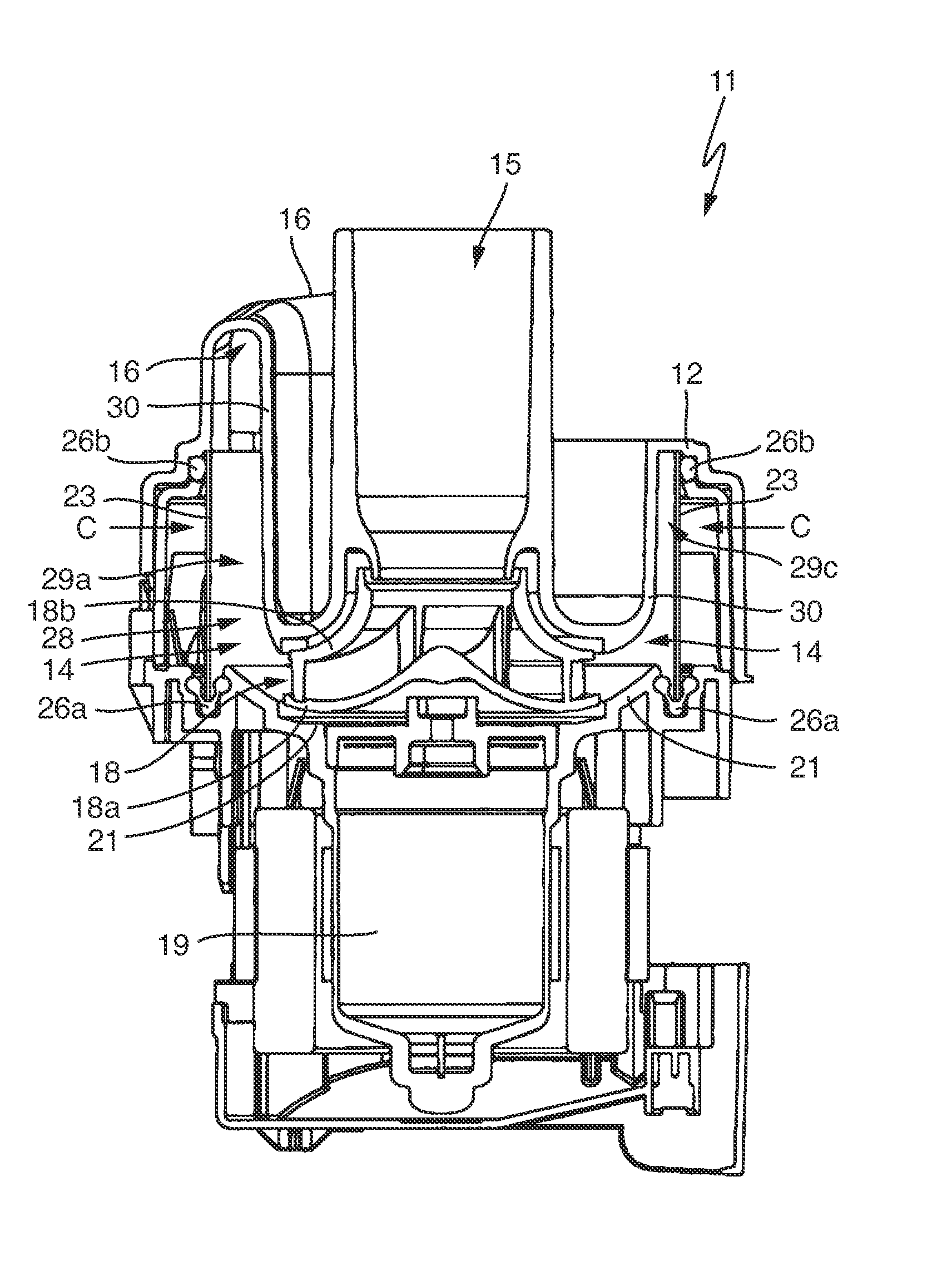
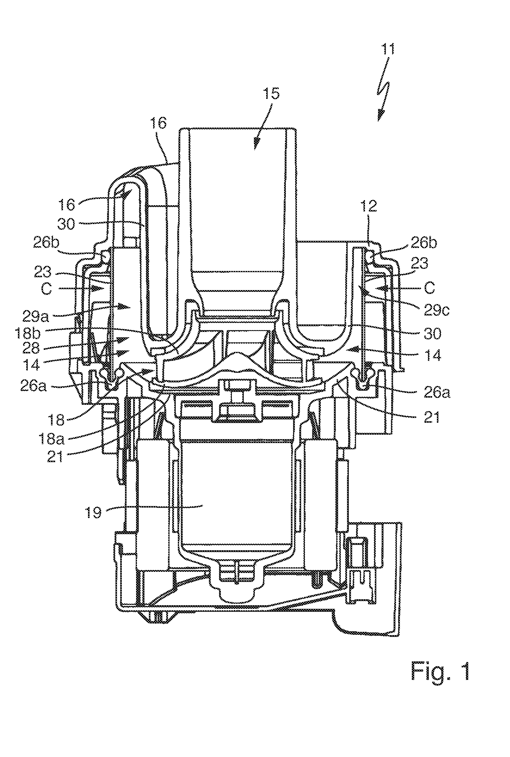
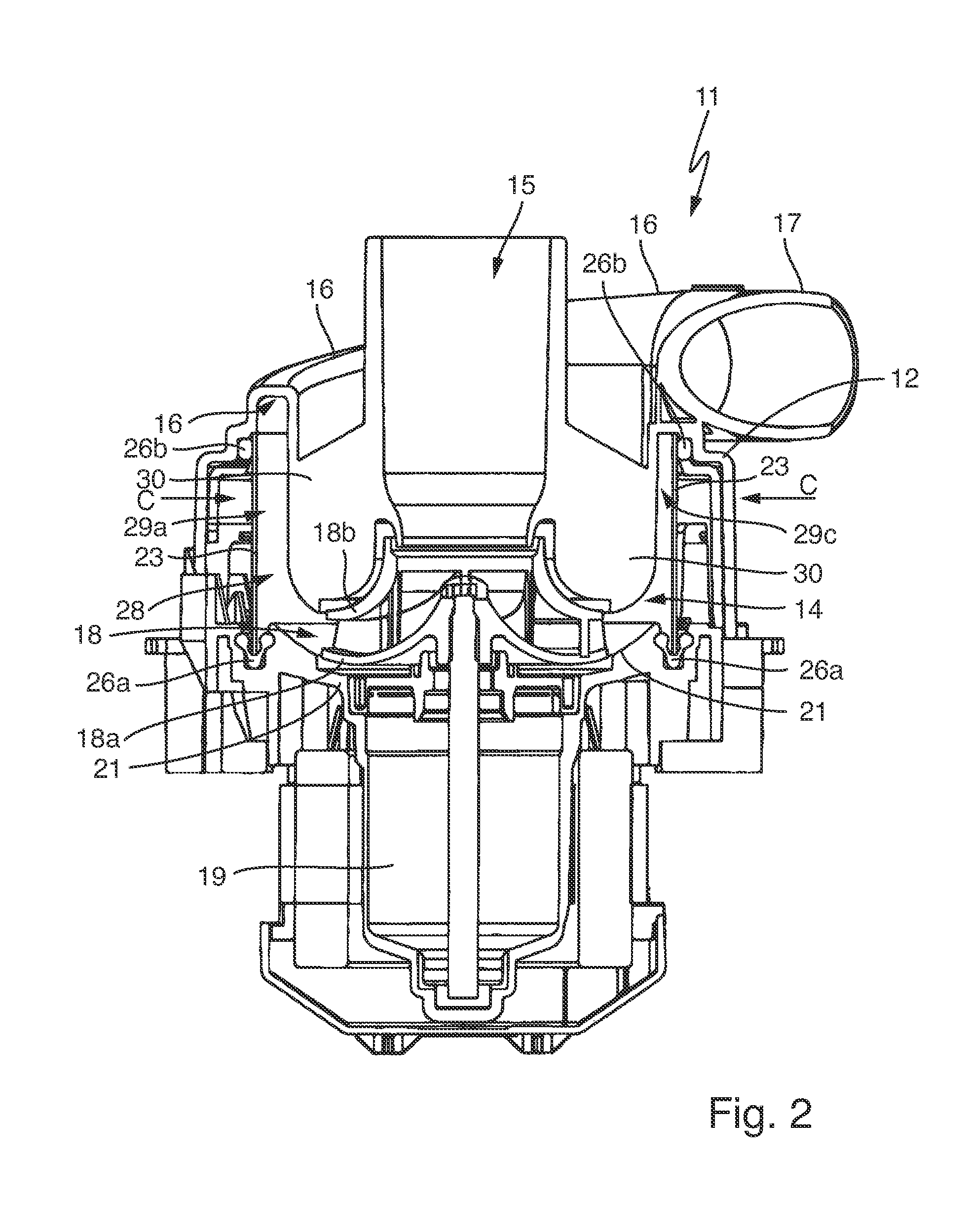
[0025]In FIG. 1 a pump 11 with a pump housing 12 is shown as generally known from the aforementioned prior art. The pump housing 12 comprises a pump chamber 14 and a central axial suction pipe 15 leads into said chamber and an outlet 16 leads out of said chamber in the tangential direction. The suction pipe 15 leads exactly towards a centrally arranged impeller 18 with a lower cover plate 18a and an upper cover plate 18b. The impeller 18 is driven by a pump motor 19 and extends above a pump chamber bottom 21 having a step-like, central depression adapted to the lower cover plate 18a.

[0026]The radially exterior wall of the pump chamber 14 is formed by a tubular heating device 23 as for example known from U.S. Pat. No. 8,245,718 B, namely as a metallic tube having a constant diameter with the ends cut off in a straight manner. On the exterior side of the tube, heating elements not shown are provided for the heating device 23, advantageously thick-film heating elements.

[0027]The heati...


PUM


Abstract

An impeller radial pump includes a pump chamber with a central suction and with a pump chamber outlet, wherein an impeller is provided in the pump chamber. Radially outside of the impeller, a circular ring shaped and circumferential pump chamber ring section is provided as a part of the pump chamber, wherein the pump chamber ring section essentially has an extension along the axial direction of the pump from the impeller against the suction direction. The pump chamber ring section has a varying width and is configured to be narrower in a compression region in the circulation direction.

Description

CROSS-REFERENCE TO RELATED APPLICATIONS[0001]This application claims priority to German Application No. 10 2012 210 554.9, filed Jun. 22, 2012, the contents of which are hereby incorporated herein in its entirety by reference.TECHNOLOGICAL FIELD[0002]The invention relates to a pump as can well be used in particular for home appliances such as dish washers or washing machines, wherein the pump is configured as a radial pump.BACKGROUND[0003]Such radial pumps are known for example from U.S. Pat. No. 8,245,718 B. They comprise a pump chamber with a central suction pipe and a pump chamber outlet, wherein an impeller rotates in the pump chamber in order to transport fluid from the suction pipe in the radial direction out of the impeller into the pump chamber and after several circulations in the pump chamber out of the same via the pump chamber outlet. Outside the impeller or in the fluid path, so to say downstream of the impeller, in the pump chamber an essentially circular ring shaped p...

Claims


Application Information

Patent Timeline
Patent Type & Authority Patents(United States)
IPC IPC(8): F03B11/02A47L15/42F04D29/58F04D29/44D06F39/08
CPCF04D29/445A47L15/4225D06F39/085F04D29/588A47L15/42D06F39/08F04D29/22F04D29/426F04D29/586F05D2210/11
Inventor ALBERT, TOBIASKOEGEL, UWE
Owner E G O ELEKTRO GERAETEBAU GMBH
Why Eureka
Try Eureka