Relay system having dual relays configured as heat sinks for one another

a relay and heat sink technology, applied in the direction of relays, charging stations, transportation and packaging, etc., can solve the problems of relay malfunction and/or melt, and both remedies have undesired attributes

Active Publication Date: 2016-10-18
LEAR CORP
View PDF28 Cites 9 Cited by
  • Summary
  • Abstract
  • Description
  • Claims
  • Application Information

AI Technical Summary

Benefits of technology

[0011]An on-board charging system for an electric vehicle having a traction battery and a powertrain includes a first relay, a second relay, and a controller. The first relay is for transferring current from an off-board charging station to the traction battery to charge the traction battery. The second relay is for transferring

Problems solved by technology

A problem occurs when the thermal equilibrium temperature is higher than what the relay system component

Method used


Image

  • Relay system having dual relays configured as heat sinks for one another
  • Relay system having dual relays configured as heat sinks for one another
  • Relay system having dual relays configured as heat sinks for one another

Examples


Embodiment Construction

[0020]Detailed embodiments of the present invention are disclosed herein; however, it is to be understood that the disclosed embodiments are merely exemplary of the invention that may be embodied in various and alternative forms. The figures are not necessarily to scale; some features may be exaggerated or minimized to show details of particular components. Therefore, specific structural and functional details disclosed herein are not to be interpreted as limiting, but merely as a representative basis for teaching one skilled in the art to variously employ the present invention.

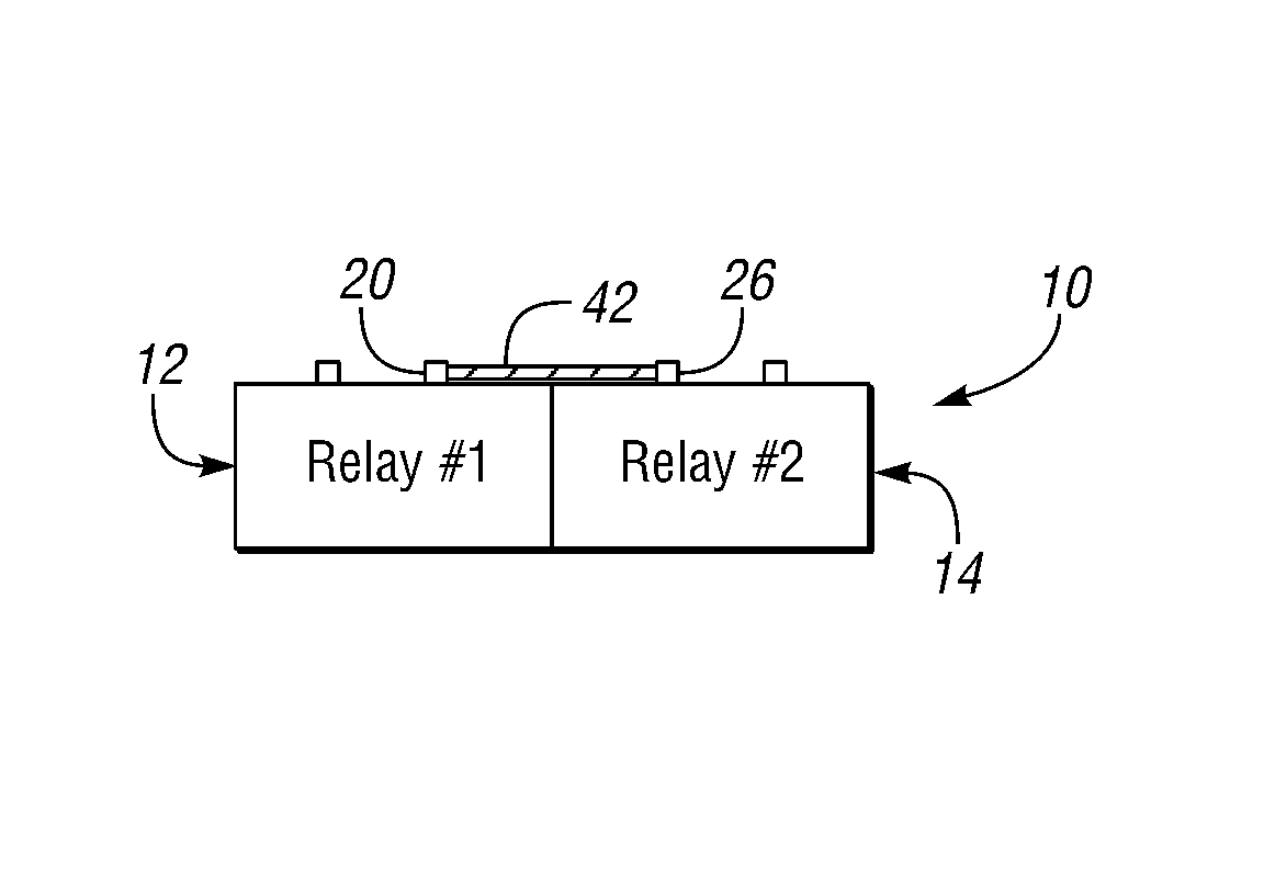
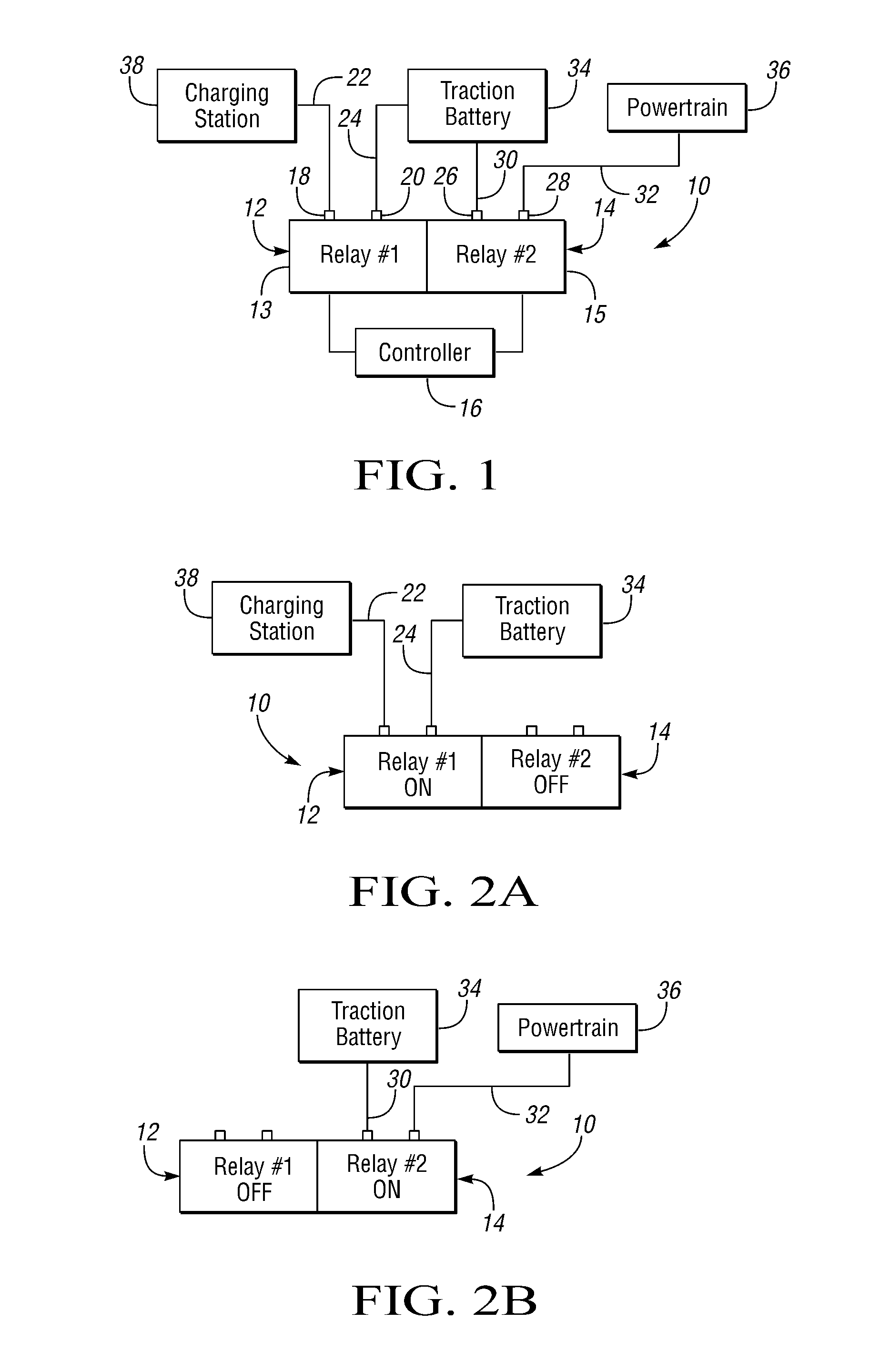
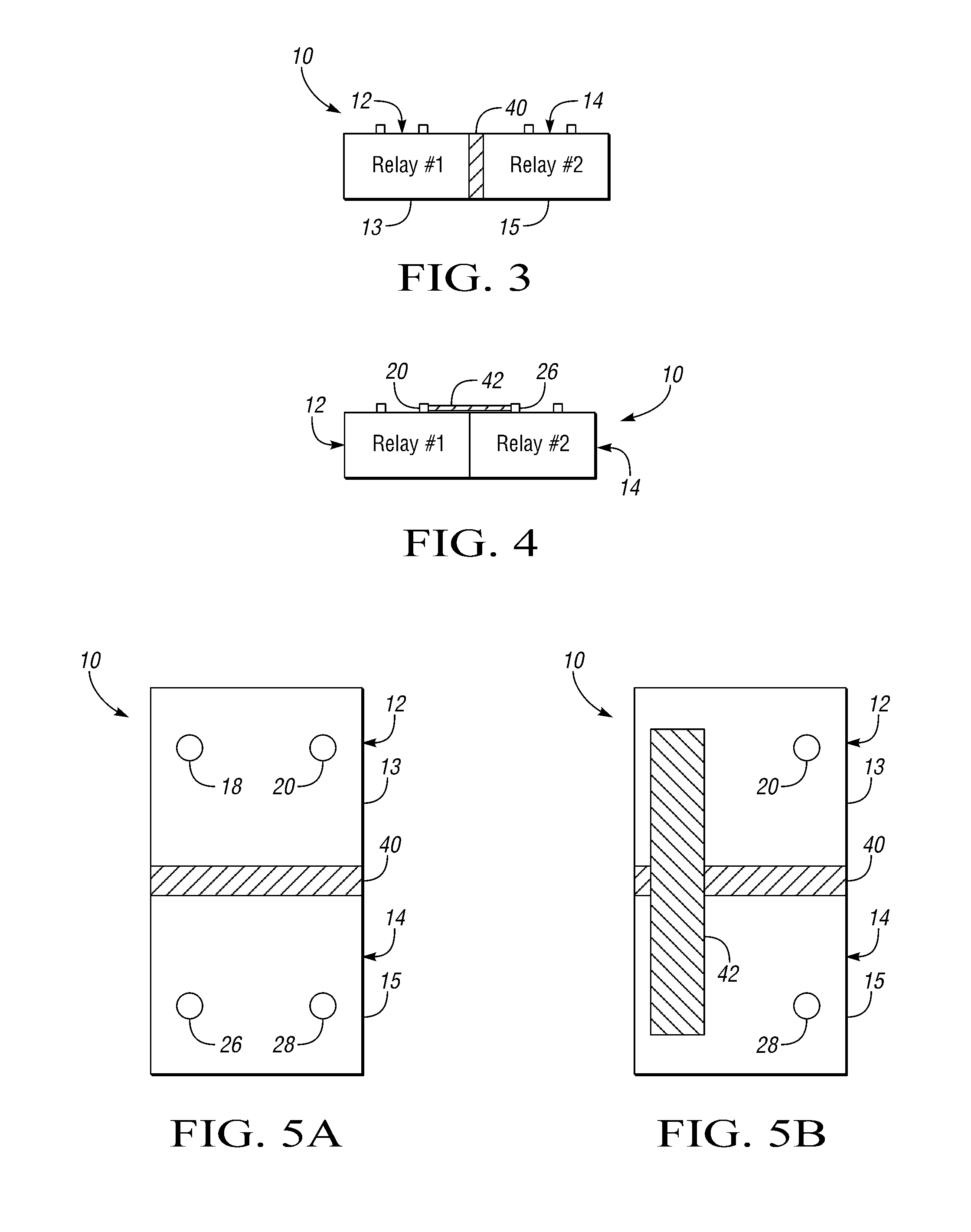
[0021]Referring now to FIG. 1, a block diagram of a relay system 10 is shown. Relay system 10 includes a first relay 12 and a second relay 14. As will be described in greater detail, first and second relays 12 and 14 are physically connected to one another such that each relay functions as a heat sink for the other relay. During operation of relay system 10, relays 12 and 14 are controlled such that one of th...


PUM


Abstract

A system includes first and second relays which physically adjoin one another and are controlled such that one of the relays is off whenever the other relay is on. In operation, heat generated in the first relay thermally conducts to the second relay where the relays physically adjoin one another whereby the second relay functions as a heat sink for the first relay while the second relay is off and the first relay is on. Correspondingly, in operation, heat generated in the second relay thermally conducts to the first relay where the relays physically adjoin one another whereby the first relay functions as a heat sink for the second relay while the first relay is off and the second relay is on.

Description

TECHNICAL FIELD[0001]The present disclosure relates to relay systems having dual relays.BACKGROUND[0002]A relay is a switch. In use, for example, a relay is connected at one end to a source and at another end to a load. When switched on, the relay is closed and connects the source to the load. In this case, electrical energy (e.g., current) may flow from the source through the relay to the load. When switched off, the relay is opened and disconnects the source from the load. In this case, no current may flow from the source to the load via the relay. This is because the source and the load are electrically isolated from one another by the relay.[0003]Current flowing through a relay generates heat. Some of the heat transfers away from the relay. The heat dissipates through the relay system until thermal equilibrium is achieved. A problem occurs when the thermal equilibrium temperature is higher than what the relay system components can handle. In this case, the relay can malfunction ...

Claims


Application Information

Patent Timeline
IPC IPC(8): H02J7/00H01H45/12B60L11/18H01H45/02
CPCH01H45/12B60L11/1818H01H45/02H01H2231/026B60L53/16H01H50/12H01H50/14Y02T10/70Y02T10/7072Y02T90/14
Inventor LOPEZ, ADRIANANGLIN, ARIC HENDERSONPATALON, CHRISTOPHER
Owner LEAR CORP
Why Eureka
Try Eureka