Diaphragm valve

Active Publication Date: 2016-10-25
FESTO AG & CO KG
View PDF25 Cites 0 Cited by
  • Summary
  • Abstract
  • Description
  • Claims
  • Application Information

AI Technical Summary

Benefits of technology

[0025]The diaphragm valve is expediently equipped with electrically actuable drive means, which serve for actuation of the valve member and which in particular facilitate the driving of the diaphragm carrier to perform its switchover

Problems solved by technology

A disadvantage of the known diaphragm valve lies in the fact that, during switchover of the valve member, the sealing diaphragm is for a time heavily stretched and therefore subject to great stress, which may have a disadvantageous effect on its service life.
With this diaphragm valve too there is the problem that the flexible sealing diaphragm, especially in the diaphragm section extending between the diaphragm carrier and the fixed edge section, is heavily stretched and su

Method used


Image

  • Diaphragm valve
  • Diaphragm valve
  • Diaphragm valve

Examples


Embodiment Construction

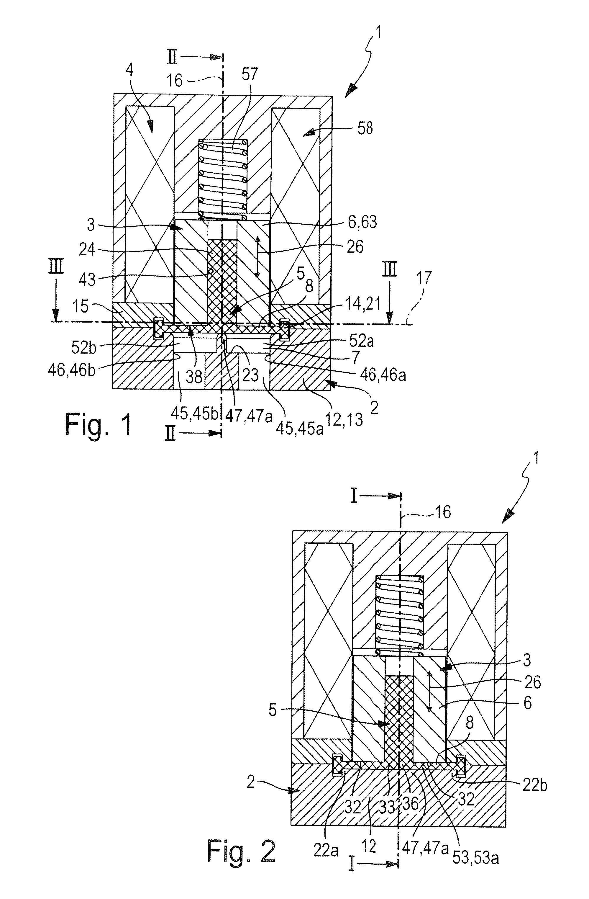
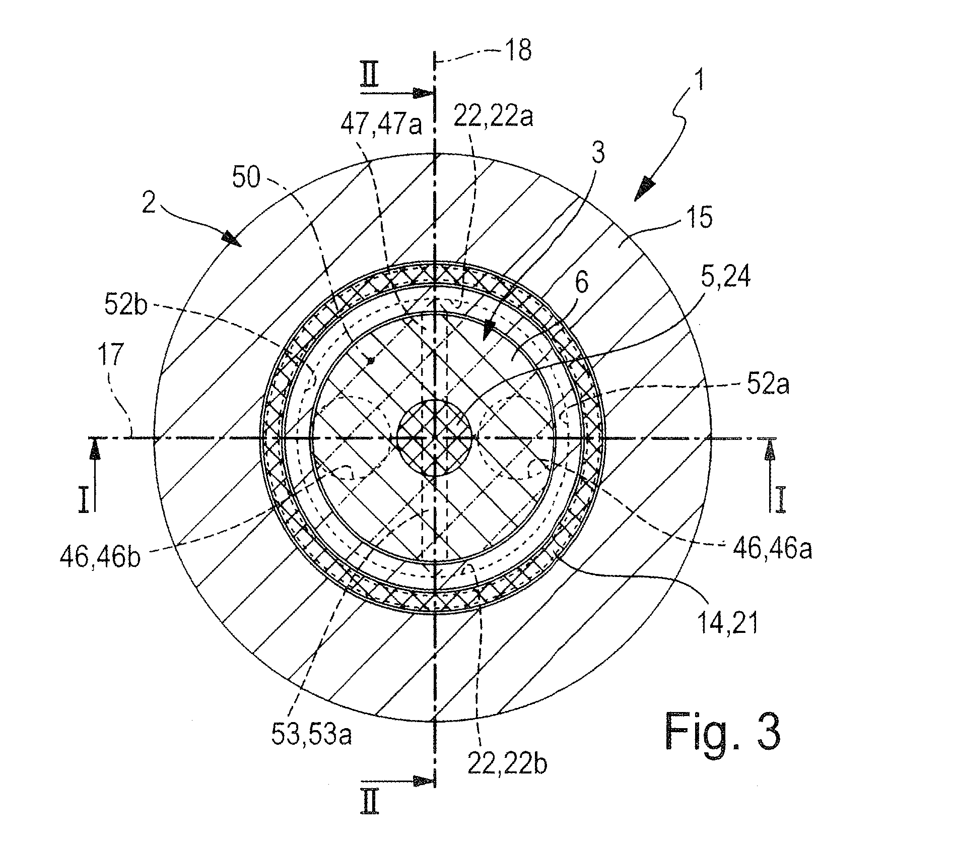
[0039]The diaphragm valve designated in its totality by reference number 1 has in all embodiments a valve housing 2 and a valve member 3 mounted in and movable relative to the valve housing 2. In addition, the diaphragm valve 1 is equipped with electrically actuable drive means 4, preferably accommodated in the interior of the valve housing 2 and through which the valve member 3 may be switched between two possible switching positions. FIGS. 1 and 2 together with 7 and 8 show in each case a first switching position, which involves a closed position. FIGS. 4 to 6 plus 10 and 11 show in each case a second switching position, involving by way of example an open position.

[0040]The valve member 3 is preferably designed as a composite element, comprised of a diaphragm body 5 and at least one diaphragm carrier 6 carrying the diaphragm body 5. These components are fastened together in a manner to be explained below. Whereas the diaphragm carrier 6 is made of a stiff material, for example of...


PUM


Abstract

A diaphragm valve has a valve housing and a valve member movable relative to said housing. The valve member includes a diaphragm carrier that can be driven to execute a switchover motion having a sealing diaphragm mounted thereon, which delimits a valve chamber in which a valve seat is found. The sealing diaphragm has a sealing section opposite said valve seat belonging at least partially to a loose diaphragm section of the sealing diaphragm, which can lift from the diaphragm carrier to reduce the stress on the sealing diaphragm when said diaphragm carrier is removed from the valve seat during switching.

Description

[0001]This application claims priority based on an International Application filed under the Patent Cooperation Treaty, PCT / EP2013 / 000715, filed Mar. 11, 2013, which claims priority based on German Patent Application No. DE102012005093.5, filed Mar. 14, 2012.BACKGROUND OF THE INVENTION[0002]The invention relates to a diaphragm valve, having a valve housing and at least one valve member movable relative to this housing, wherein the valve member has a diaphragm carrier movable relative to the valve housing through the execution of a switchover movement and also a flexible sealing diaphragm which, together with the valve housing, bounds a valve chamber, wherein the sealing diaphragm is fixed to the valve housing under sealing at its outer edge section and has a mounting diaphragm section fastened to the diaphragm carrier with clearance from said outer edge section and accompanying the switchover movement, wherein there is mounted in the valve chamber a valve seat facing the sealing dia...

Claims


Application Information

Patent Timeline
IPC IPC(8): F16K31/06F16K31/02F16K7/12
CPCF16K7/12F16K7/126F16K31/02F16K31/0641F16K31/0672F16K31/10F16K7/14
Inventor BUHLER, ANDREAS
Owner FESTO AG & CO KG
Why Eureka
Try Eureka