Method of digitally constructing a prosthesis

a digital construction and prosthetic technology, applied in the field of prosthetics, can solve the problems of soft tissue breakdown of the residual limb, further disability, and inability to fit the prosthetic socket properly,

Active Publication Date: 2016-11-01
LAYMAN WILLIAM STRATFORD +1
View PDF19 Cites 8 Cited by
  • Summary
  • Abstract
  • Description
  • Claims
  • Application Information

AI Technical Summary

Benefits of technology

[0021]Therefore, it is a principal object of the present invention to provide a prosthesis and a method to fabricate a prosthesis constructed of a plastic material such as ULTEM®, or carbon fiber, or other material of equivalent or greater strength that may be known or developed in the future, through the use of digital manipulation of a file that has captured the alignment and the socket measurements, then created a definitive prosthesis by a method which can be done in an efficient rate and manner than the conventional methods which are time consuming.

Problems solved by technology

If these criteria are not achieved, when the patient uses the prosthesis, residual limb soft tissue breakdown often occurs.
The result is painful sores, blisters, ulcers, or cysts on the residual limb that typically restrict continued prosthesis use, and in severe cases, necessitate a further amputation to a higher anatomical level, which can lead to further disability.
The principal cause of such breakdown is a poorly fitting prosthetic socket.
Practitioners face challenges in making quality sockets for the increasing amputee popularity.
Also, there is a shortage of prosthetists in the industry, and that shortage is expected to increase in the future, as the demand for prosthetic devices increases.

Method used


Image

  • Method of digitally constructing a prosthesis
  • Method of digitally constructing a prosthesis
  • Method of digitally constructing a prosthesis

Examples


Embodiment Construction

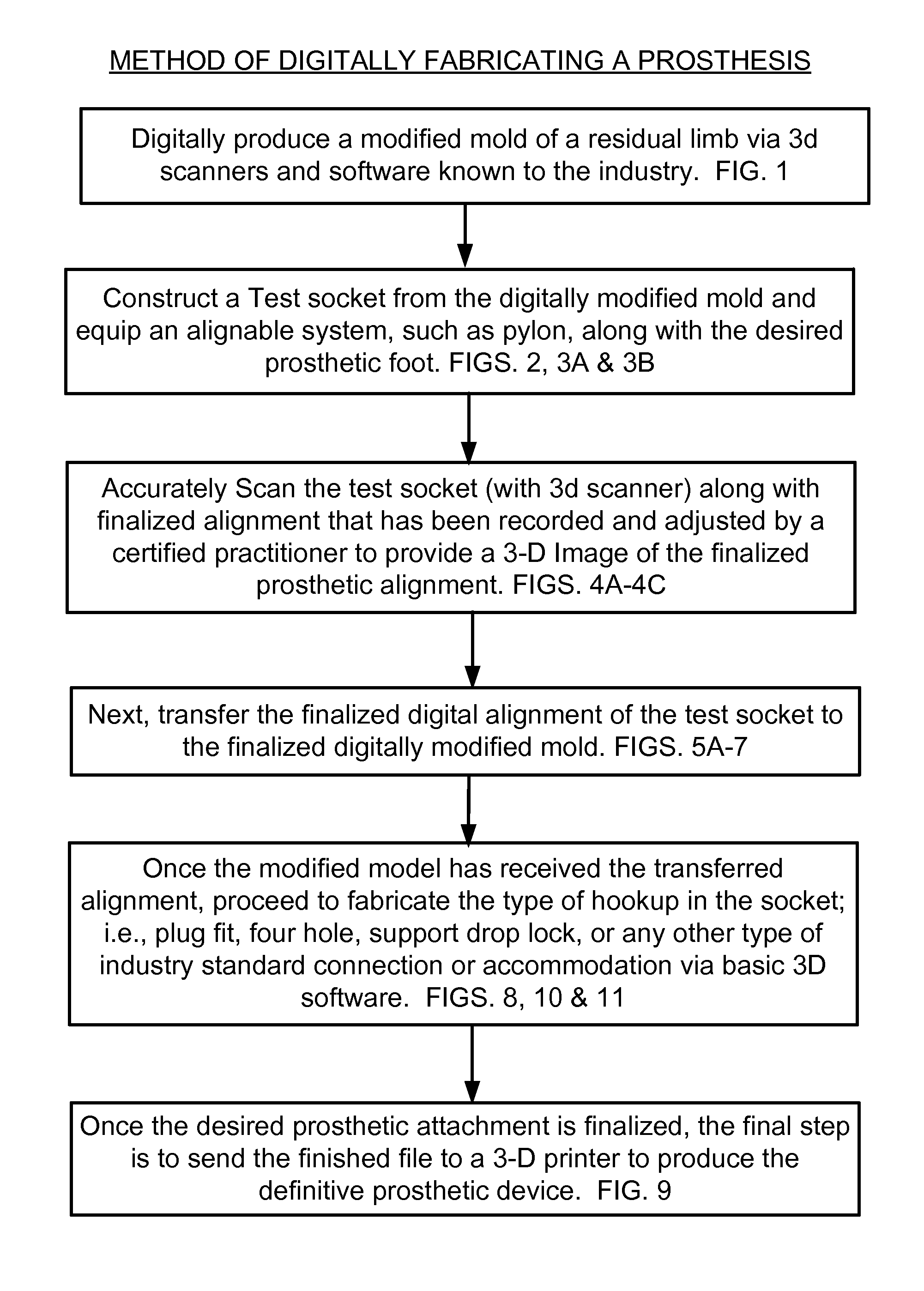
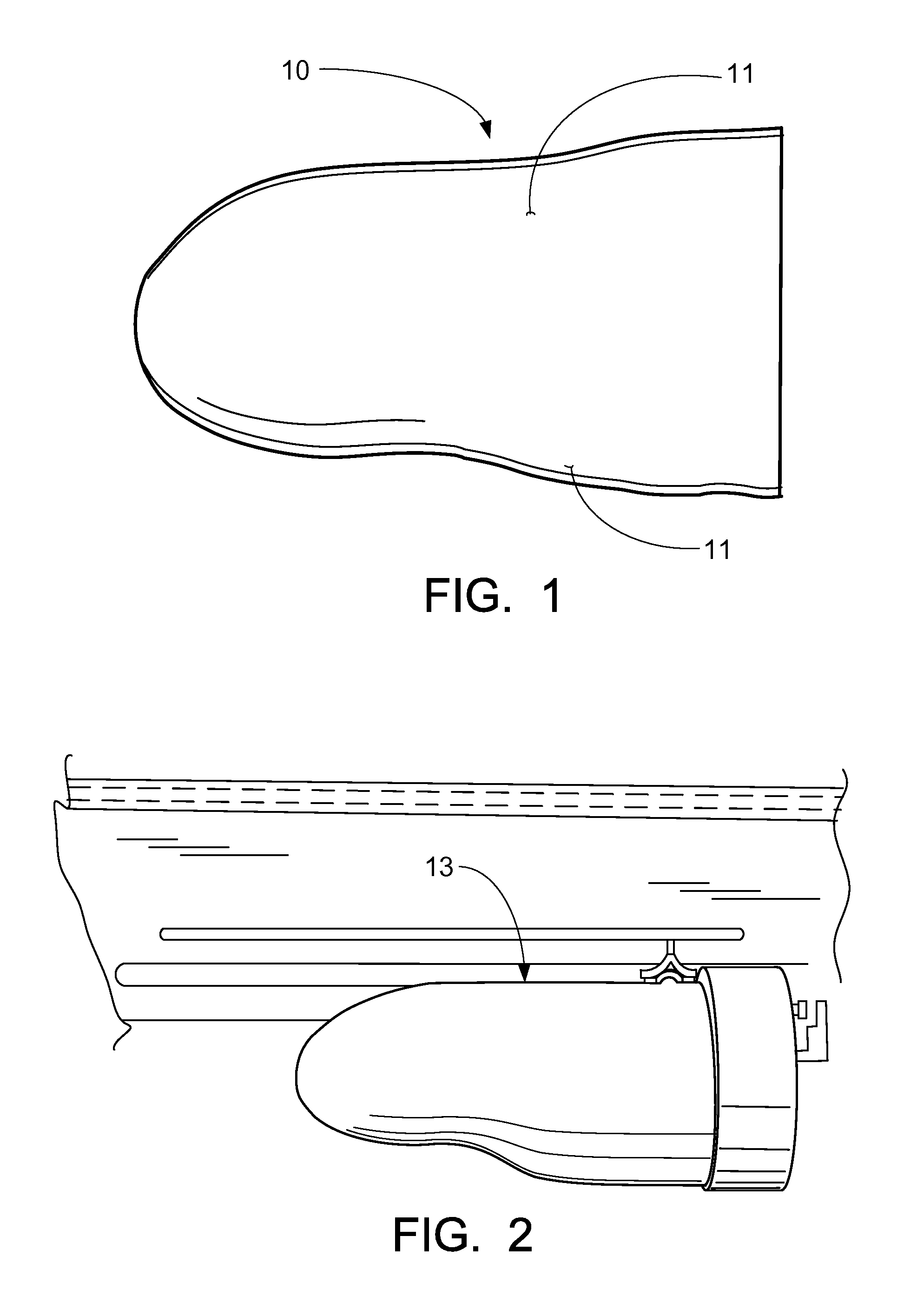
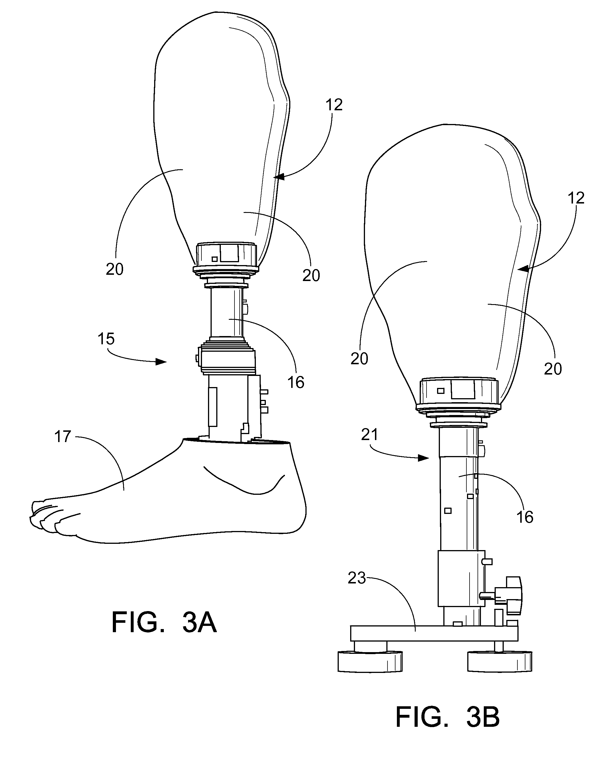
[0035]FIGS. 1 through 12 illustrate a preferred embodiment of the method or process of constructing a prosthetic limb through a digital format.

[0036]Before reference is made to the Figures, in general, this technique of achieving a positive mold for a test socket in a digital format is by scanning the residual limb. The first step would be to choose the materials and tools needed for measuring a patient. Again, one would need to prepare suspension of the prosthesis (silicone liner, foam or other types of socket designs); a scanner; a laptop; reflective dots; measuring tools such as a length stick M / L gauge tape measure, etc. The method may vary by which Distal Device used.

[0037]After preparing oneself with the items one would need to take a digital image of a residual limb, the individual would use a scanner to capture the digital image of the limb. After the limb is captured, the individual would use a prosthetic software which is already known in the art, to modify the 3-D image o...


PUM


Abstract

A prosthetic limb and process to digitally construct a prosthetic limb which includes first, digitally producing a modified mold of a residual limb via 3d scanners and software; constructing a test socket from the digitally modified mold and be equipped with an alignable system; accurately scanning the test socket, along with finalized alignment that has been recorded and adjusted by a certified practitioner to provide a 3-D Image of the finalized prosthetic alignment; transferring the finalized digital alignment of the test socket to the finalized digitally modified mold; once the modified model has received the transferred alignment, fabricating the type of hookup in the socket; i.e., plug fit, four hole, support drop lock, or any other type of industry standard connection or accommodation via basic 3D software; and once the desired prosthetic attachment is finalized, sending finished file to a 3-D printer to produce the definitive prosthetic device.

Description

CROSS-REFERENCE TO RELATED APPLICATIONS[0001]This is a nonprovisional patent application of U.S. Provisional Patent Application Ser. No. 61 / 674,720, filed Jul. 23, 2012, which is hereby incorporated herein by reference.[0002]Priority of U.S. Provisional Patent Application Ser. No. 61 / 674,720, filed Jul. 23, 2012, incorporated herein by reference, is hereby claimed.STATEMENT REGARDING FEDERALLY SPONSORED RESEARCH OR DEVELOPMENT[0003]Not applicableREFERENCE TO A “MICROFICHE APPENDIX”[0004]Not applicableBACKGROUND OF THE INVENTION[0005]1. Field of the Invention[0006]The present invention relates to prosthetics. More particularly, the present invention relates to a novel process for constructing a prosthetic limb through a series of fabrication steps including retrieving a file from a computer, manipulating that file that has captured alignment and socket fit, sending it to a 3D printer, which in turn has the ability to print out a completed, wearable prosthetic limb of strong plastic m...

Claims


Application Information

Patent Timeline
Patent Type & Authority Patents(United States)
IPC IPC(8): A61F2/50
CPCA61F2/5046A61F2002/5049
Inventor LAYMAN, WILLIAM STRATFORDLAYMAN, W. BRIAN
Owner LAYMAN WILLIAM STRATFORD
Why Eureka
Try Eureka