Method for producing flexible EAP generators

a generator and flexible technology, applied in piezoelectric/electrostrictive devices, piezoelectric/electrostrictive/magnetostrictive devices, device details, etc., can solve the problem of only effective eap stacks, and achieve the effect of precise positioning of electrodes on top and precise positioning of electrodes

Active Publication Date: 2016-11-01
ROBERT BOSCH GMBH
View PDF13 Cites 0 Cited by
  • Summary
  • Abstract
  • Description
  • Claims
  • Application Information

AI Technical Summary

Benefits of technology

[0011]The individual windings of the spiral resulting from the winding process are joined to each other or held together. For this purpose, in each case two immediately consecutive windings may be glued, welded or sealed to each other. However, it is also possible to introduce the spiral-shaped stacks into a flexible envelope, such as a hose, and to close the same at its opposing ends, so that a gap formation between the individual windings of the EPA stack is prevented. The latter specific embodiment has the advantage that the EAP stack is protected from harmful environmental influences.
[0015]To ensure the integrity and functionality of the ring or cylinder sectors in the EAP stack, precise positioning of the electrodes on top of each other is important, since the deflection of the EAP stack may only be efficiently converted into electrical energy in the case of precise congruent positioning of the electrodes on top of each other. To achieve this, the strip is wound around a rod in one preferred specific embodiment of the method according to the present invention. In the simplest specific embodiment, the rod has a circular or oval cross section. The rod preferably has a triangular, quadrangular, polygonal or star-shaped cross section, the strip on its side which determines the inner circumference of the spiral having projections and / or recesses, which are designed in such a way that form-locked winding of the strip with the rod and around the rod may be carried out. In the method according to the present invention, the strip is therefore wound with the rod around the rod in a form-locked manner. The use of such rods as a winding core, which is removable from the interior of the spiral after the spiral has been manufactured, allows precise positioning of the electrodes.

Problems solved by technology

However, these EAP stacks are only effective with a deformation in the direction of their longitudinal axis, but not during deflection.

Method used


Image

  • Method for producing flexible EAP generators
  • Method for producing flexible EAP generators
  • Method for producing flexible EAP generators

Examples


Embodiment Construction

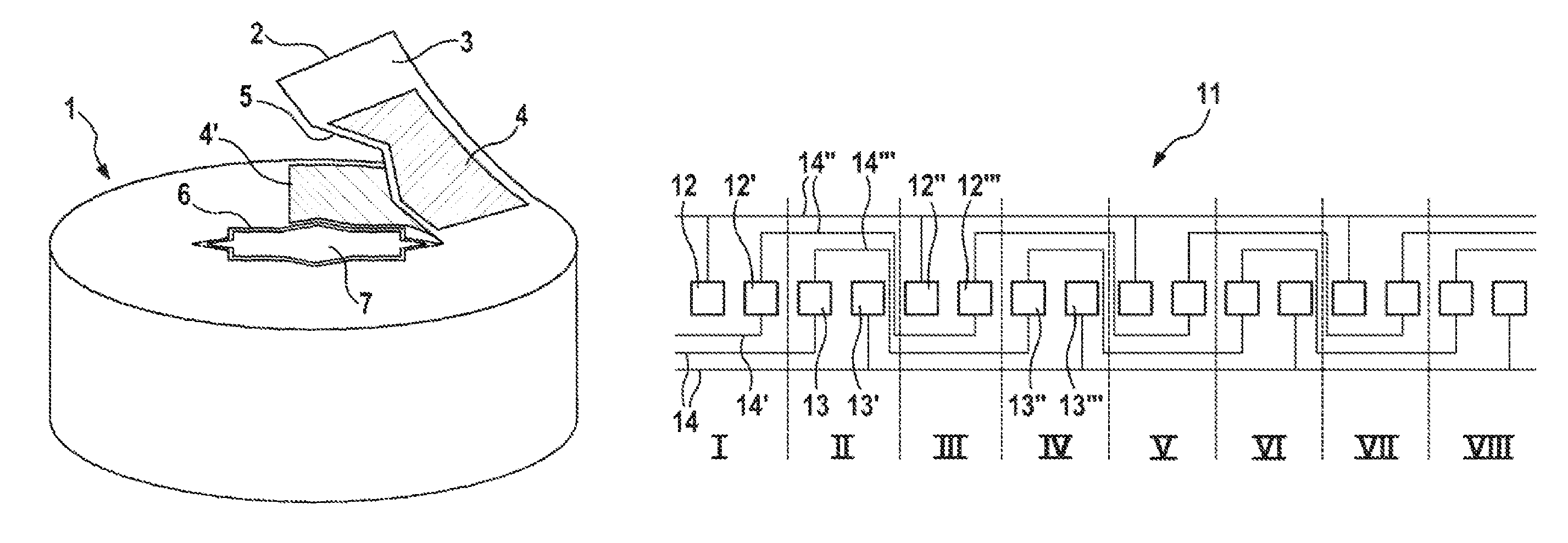
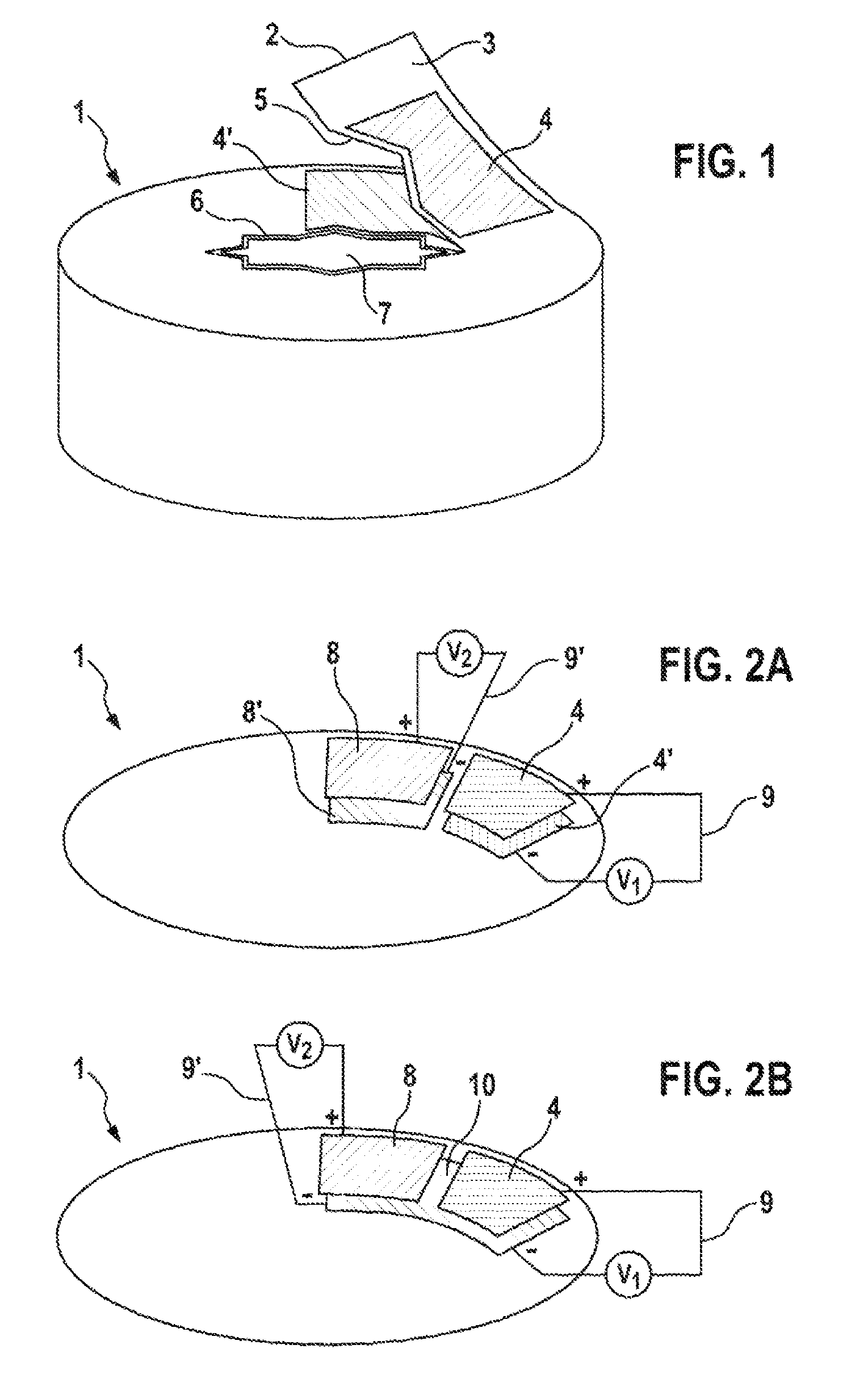
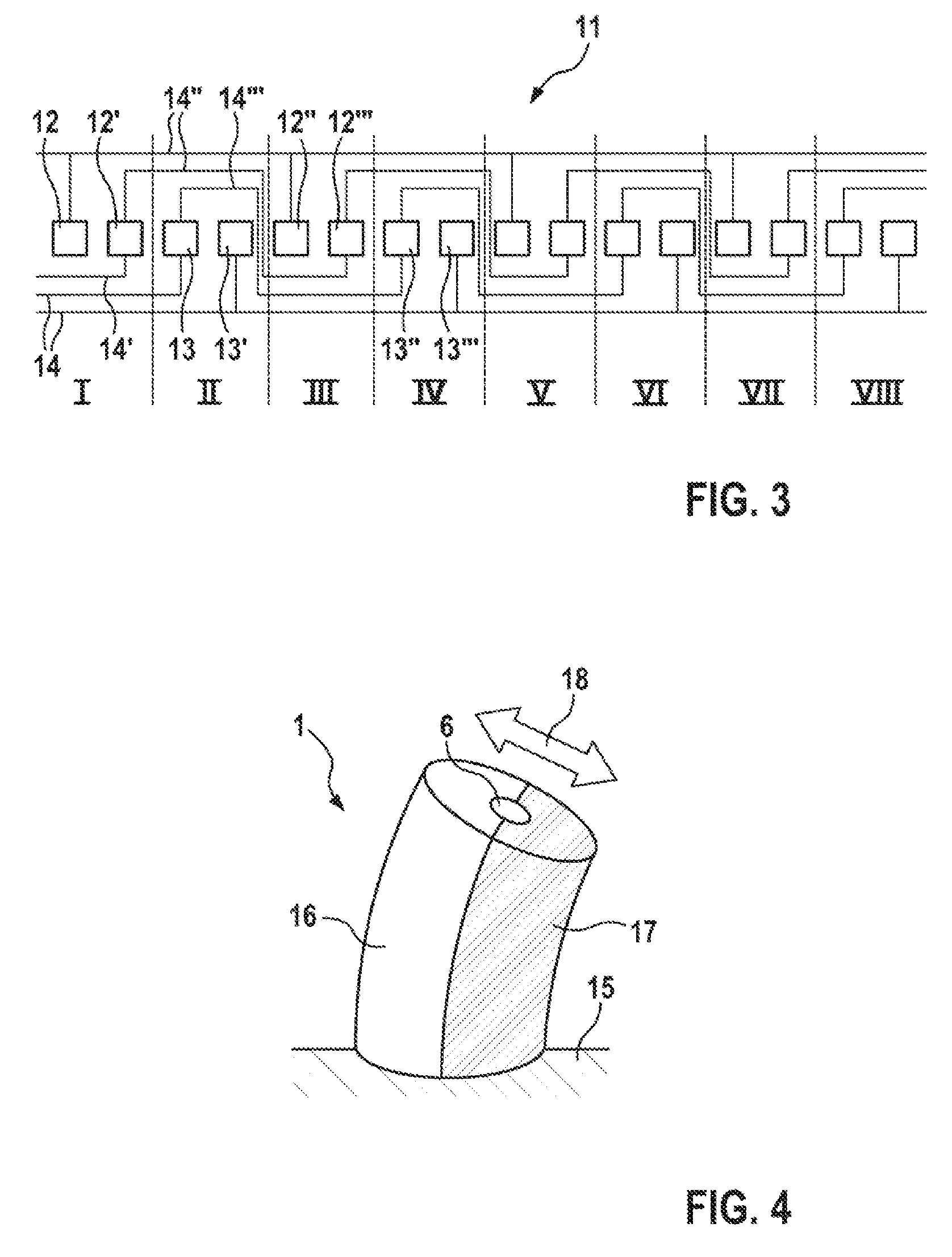
[0030]FIG. 1 shows a schematic sketch of a spirally composed EAP stack. EAP stack 1 is based on a strip 2 which is spirally wound. Strip 2 includes a layer 3 made of electroactive polymer and planar electrodes 4, 4′ applied to sections of this layer 3. Strip 2 is spirally wound in such a way that two planar electrodes 4, 4′ which are not immediately consecutive are situated congruently on top of each other, a layer 3 made of electroactive polymer being situated in each case between two electrodes which are situated congruently on top of each other.

[0031]The circumference of EAP stack 1 shown is circular; however, it may also have a different cross-sectional shape. Strip 2 is spirally wound in such a way that a cavity 5 is created, which is delimited by the inner circumference of spiral 1. Cavity 6 extends in the longitudinal direction of EAP stack 1 along the longitudinal axis of EAP stack 1. In the specific embodiment shown, cavity 6 does not have a circular cross section, but a st...


PUM


Abstract

In a method for manufacturing electroactive polymer generators, a strip, including one layer of an electroactive polymer and electrodes applied to sections of this layer, is spirally wound in such a way that multiple electrodes are situated congruently on top of each other, in each case two electrodes situated on top of each other being separated from each other by a layer of electroactive polymer.

Description

BACKGROUND OF THE INVENTION[0001]1. Field of the Invention[0002]The present invention relates to a method for producing flexible electroactive polymer generators.[0003]2. Description of the Related Art[0004]Electroactive polymers (EAP) are polymers which change their shape when an electric voltage is applied. As a result, electroactive polymers are usable as actuators. However, electroactive polymers also allow an operation in the manner of a generator, in which a mechanically induced expansion of the electroactive polymer is directly converted into electrical energy. Such energy converters are referred to as EAP generators. The conversion of the expansion of the electroactive polymer into electrical energy takes place on a capacitive basis by the shifting of charges. During the conversion of mechanical energy into electrical energy with the aid of electroactive polymers, the EAP generator, including at least one component which has two resilient electrodes between which a tier made...

Claims


Application Information

Patent Timeline
Patent Type & Authority Patents(United States)
IPC IPC(8): H01L41/04H01L41/27H01L41/22H01L41/09H01L41/047H01L41/113H01L41/083H01L41/193
CPCH01L41/0835H01L41/0471H01L41/0966H01L41/1136H01L41/193H01L41/22H01L41/27H10N30/871H10N30/505H10N30/2046H10N30/306H10N30/05H10N30/01H10N30/857
Inventor DENES, ISTVAN
Owner ROBERT BOSCH GMBH
Why Eureka
Try Eureka