Transaxle and working vehicle equipped with the transaxle

a technology of transaxles and working vehicles, applied in fluid gearings, jet propulsion mountings, gearing, etc., can solve problems such as spoiling stability, vehicle imbalance, and vehicle problems, so as to reduce the size of fixture parts, reduce the cost of supplying components, and minimize the effect of vehicle siz

Inactive Publication Date: 2016-11-08
KANZAKI KOKYUKOKI MFG
View PDF4 Cites 4 Cited by
  • Summary
  • Abstract
  • Description
  • Claims
  • Application Information

AI Technical Summary

Benefits of technology

[0009]Due to the configuration of the transaxle, the heavy longitudinal engine can be disposed in the lateral middle portion of the vehicle so as to laterally balance the vehicle. Further, due to the assembling of the engine together with the HST and the mechanical transmission, the engine approaches the HST and the mechanical transmission, so that a common support member can be used to support the engine, the HST and the mechanical transmission, and a space for mounting the engine can be reduced so as to reduce a size of a fixture member for the engine, thereby minimizing the vehicle and reducing costs for supplying component parts. Further due to the distribution of the first and second PTO shafts, the vehicle is further minimized, and the mechanical transmission is released from a load caused by collecting PTO shafts at only one place, thereby enhancing the durability of component parts and reducing noise.
[0011]Due to the configuration of the transaxle, a level of a fluid sump in the transmission casing can be set so that only the input shaft, the transmission output shaft, and gears on the input shaft and the transmission output shaft are submerged in a fluid sump in the transmission casing. Remaining components for the mechanical transmission are disposed above the level of the fluid sump so as to be lubricated directly or via the first or second drive train with fluid splashed up from the fluid sump agitated by the gears on the input shaft and the transmission output shaft. Therefore, the fluid sump can be volumetrically reduced so as to reduce agitation resistance of the fluid and heating of the fluid, thereby reducing energy loss and running costs.
[0013]Therefore, such a dead space is used for arranging the reservoir tank, thereby ensuring the compactness of the transaxle joined to the engine and provided with the reservoir tank. The reservoir tank can be used for a stable fluid supply for hydraulic devices in the vehicle, including the HST, while a fluid sump in the inside of the transmission casing may be unstable for such a fluid supply because of tilt of the vehicle during traveling, for example. Further, due to the reservoir tank, the fluid sump in the inside of the transmission casing can be volumetrically reduced so as to reduce agitation resistance of the fluid and heating of the fluid, thereby reducing energy loss and running costs.
[0016]Due to the configuration of the vehicle, the vehicle can have the heavy longitudinal engine mounted at the lateral middle portion of the vehicle, thereby being laterally balanced. Further, due to the assembling of the engine together with the HST and the mechanical transmission, the engine approaches the HST and the mechanical transmission, so that a common support member can be used to support the engine, the HST and the mechanical transmission, and a space for mounting the engine can be reduced so as to reduce a size of a fixture member for the engine, thereby minimizing the vehicle and reducing costs for supplying component parts. Further due to the distribution of the first and second PTO shafts, the vehicle is further minimized, and the mechanical transmission is released from a load caused by collecting PTO shafts at only a place, thereby enhancing the durability of component parts and reducing noise.

Problems solved by technology

The vehicle has some problems.
First, the vehicle is wrongly balanced so as to spoil its stability in traveling because the heavy engine is disposed laterally eccentrically in the vehicle.
Second, the vehicle has to increase its size and the number of its component parts because the engine is separated from the transmission assembly and needs its own fixture member and a space separated from the transmission assembly.
Fourth, the transmission assembly has to have a portion where plural PTO shafts are collected and supported, thereby reducing durability of component parts in the portion and tending to cause noise from the portion.

Method used


Image

  • Transaxle and working vehicle equipped with the transaxle
  • Transaxle and working vehicle equipped with the transaxle
  • Transaxle and working vehicle equipped with the transaxle

Examples


Embodiment Construction

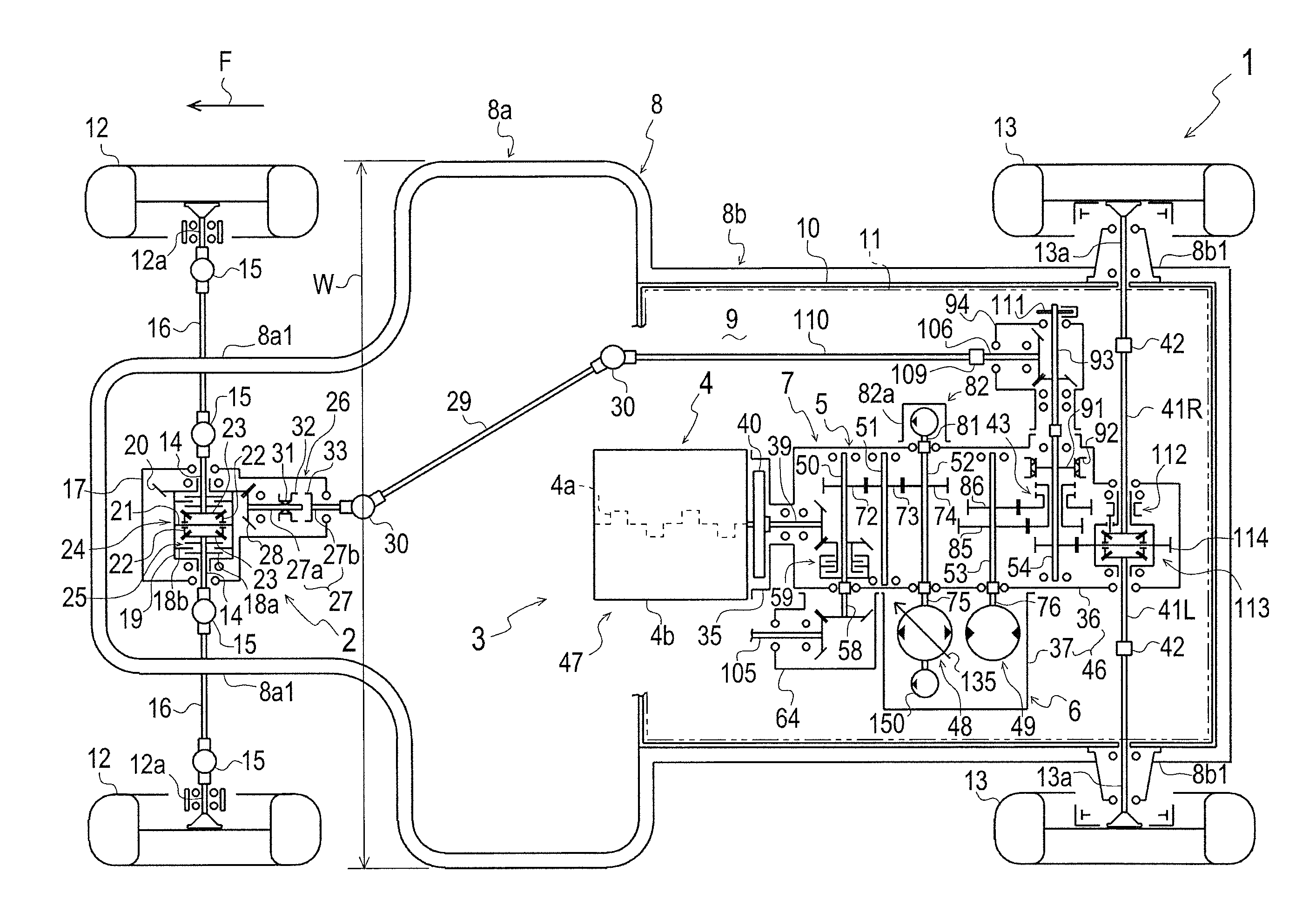
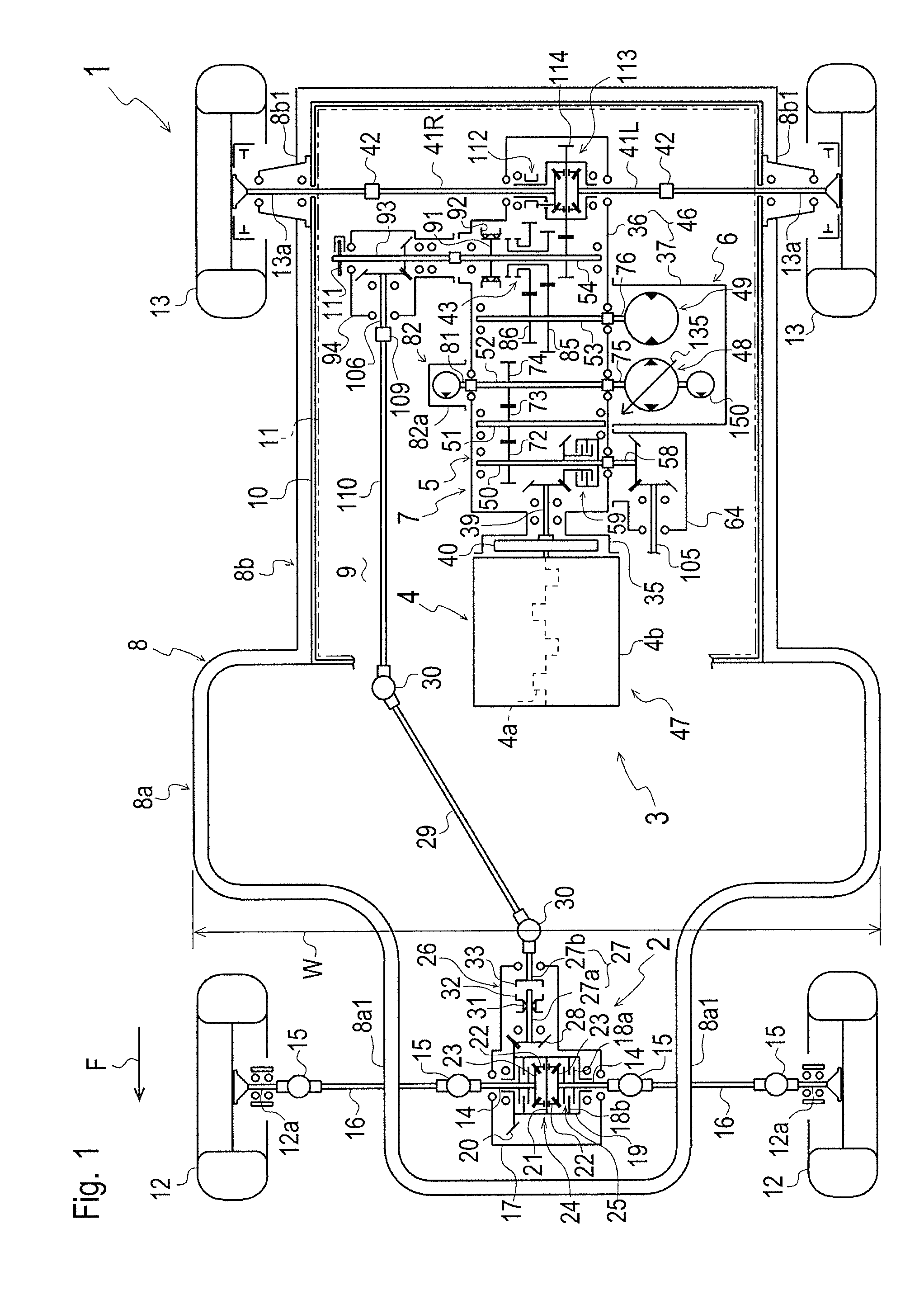
[0031]Hereinafter, descriptions will be given on an assumption that a utility vehicle 1 equipped with an engine-transaxle assembly 3 faces forward in a direction designated by an arrow F as shown in FIG. 1, and words “longitudinal” and “longitudinally” will be used on an assumption that they are only defined as meaning the fore-and-aft direction of utility vehicle 1.

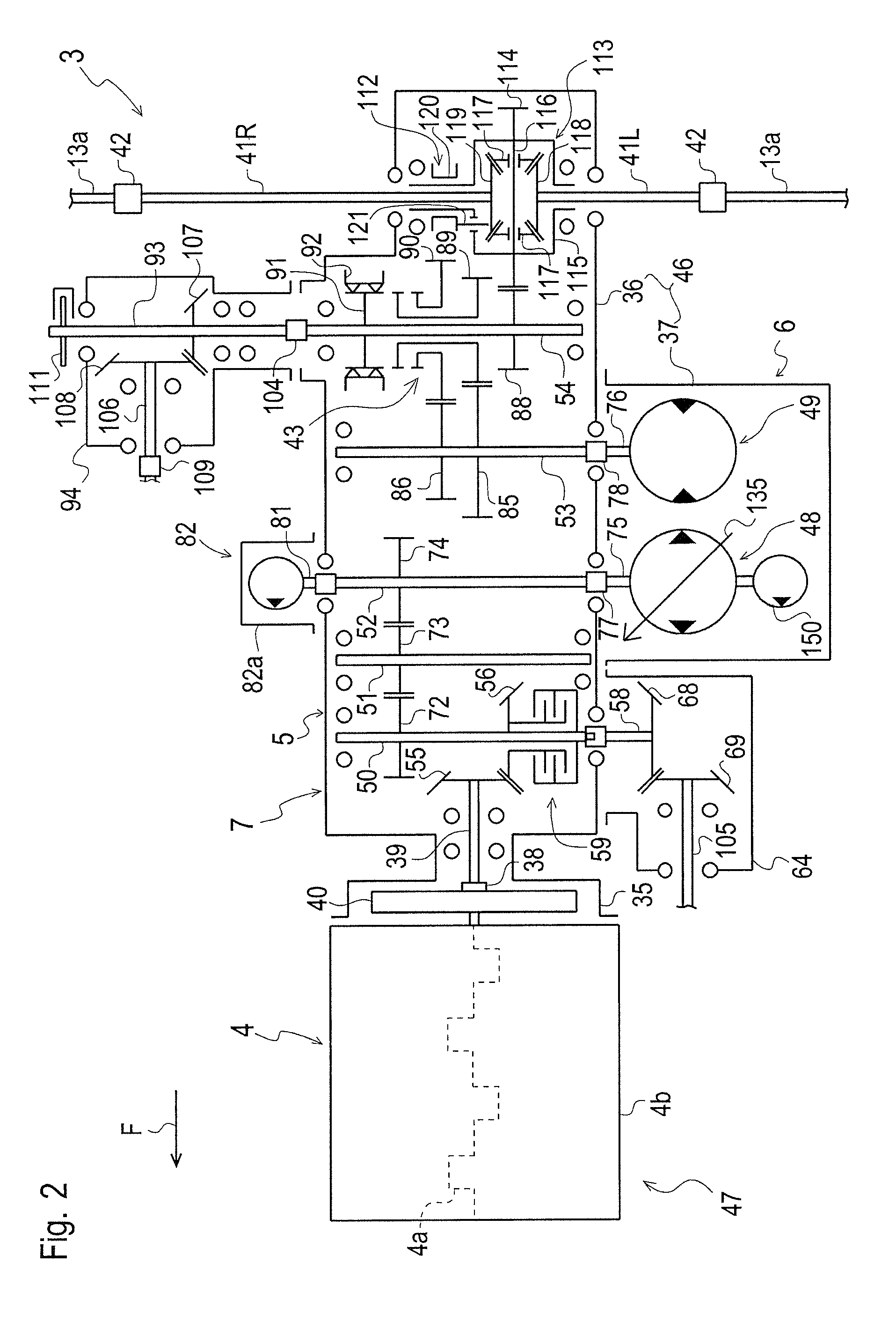
[0032]Referring to FIGS. 1 and 2, entire utility vehicle 1 will be described. Utility vehicle 1 is provided with a vehicle body frame 8 including a front frame 8a and a rear frame 8b joined to each other. A front portion of front frame 8a is laterally narrowed so as to serve as a front wheel support portion 8a1 carrying right and left front wheels 12 on right and left outer sides thereof. Rear frame 8b having a constant lateral width carries right and left rear wheels 13 on right and left outer sides of a rear portion thereof serving as a rear wheel supporting portion 8b1. A horizontal platform 9 which is substantially r...


PUM


Abstract

A transaxle is adaptable to a vehicle equipped with a longitudinal engine including an engine output shaft to be oriented in a longitudinal direction of a vehicle. The transaxle comprises a transmission output shaft to be oriented in a lateral direction of the vehicle so as to be drivingly connected to a drive wheel of the vehicle, a hydrostatic transmission and a mechanical transmission for transmitting power from the engine output shaft to the transmission output shaft, and first and second power take-off shafts for taking off power from the mechanical transmission. The engine is joined to the transaxle so that the engine, the hydrostatic transmission and the mechanical transmission are assembled together. The first and second power take-off shafts are distributed rightward and leftward from the engine.

Description

CROSS-REFERENCE TO RELATED APPLICATIONS[0001]The present application claims priority to Japanese Patent Application No. 2014-092768, filed on Apr. 28, 2014.BACKGROUND OF THE INVENTION[0002]1. Field of the Invention[0003]The present invention relates to a configuration of an apparatus serving as a transaxle for a working vehicle equipped with a longitudinal engine, and relates to a working vehicle equipped with such an apparatus.[0004]2. Related Art[0005]An engine having a horizontal engine output shaft extended in the longitudinal (i.e., fore-and-aft) direction of a vehicle is referred to as a “longitudinal engine.” There is a well-known conventional working vehicle (e.g., a utility vehicle) equipped with a longitudinal engine and a transmission assembly including a hydrostatic transmission (hereinafter, “HST”) and a mechanical transmission (e.g., a gear transmission), as disclosed by JP 2007-22379 A. In this vehicle, the HST and the mechanical transmission are configured to transmi...

Claims


Application Information

Patent Timeline
Patent Type & Authority Patents(United States)
IPC IPC(8): B60K17/346B60K17/28B60K17/10B60K17/35B60K5/02B60K5/00F16H47/02
CPCB60K17/3462B60K17/105B60K17/28B60K17/35B60K5/02B60K2005/003B60Y2300/58F16H47/02
Inventor MATSUURA, JUNIWAKI, KOJI
Owner KANZAKI KOKYUKOKI MFG
Why Eureka
Try Eureka