Compensator module for a transceiver unit, radio system and method of operating thereof

a transceiver unit and compensator technology, applied in the field of compensator modules, can solve the problem that the transmission power provided at the output of the transceiver unit is typically subject to a line loss

Active Publication Date: 2016-11-08
U-BLOX
View PDF11 Cites 9 Cited by
  • Summary
  • Abstract
  • Description
  • Claims
  • Application Information

AI Technical Summary

Problems solved by technology

A transmitter power which is provided at the output of the transceiver unit is typically subjected to a line loss before it is supplied to an antenna.

Method used


Image

  • Compensator module for a transceiver unit, radio system and method of operating thereof
  • Compensator module for a transceiver unit, radio system and method of operating thereof
  • Compensator module for a transceiver unit, radio system and method of operating thereof

Examples


Embodiment Construction

[0012]The present invention takes account of the fact that existing radio systems have previously not been satisfactorily prepared to compensate for the above-described power losses.

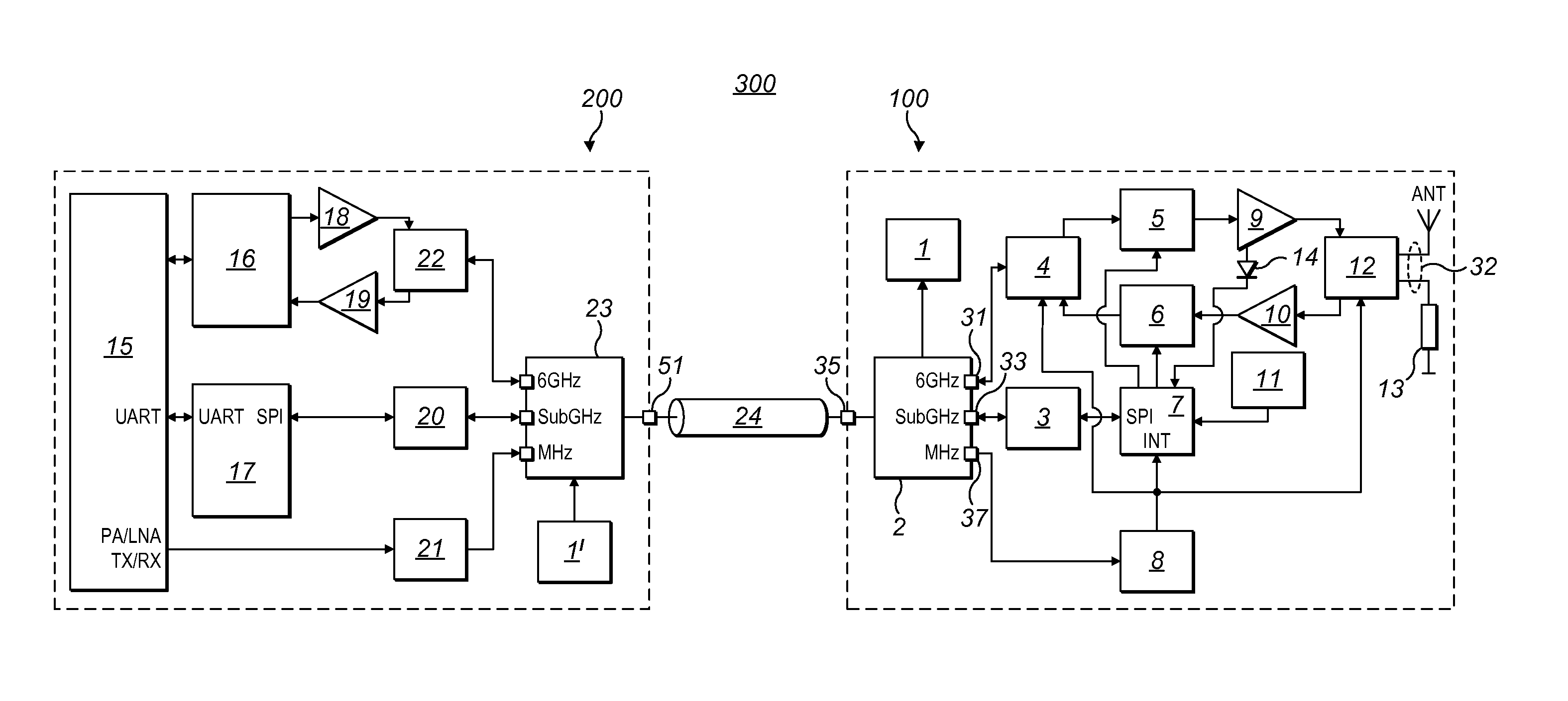
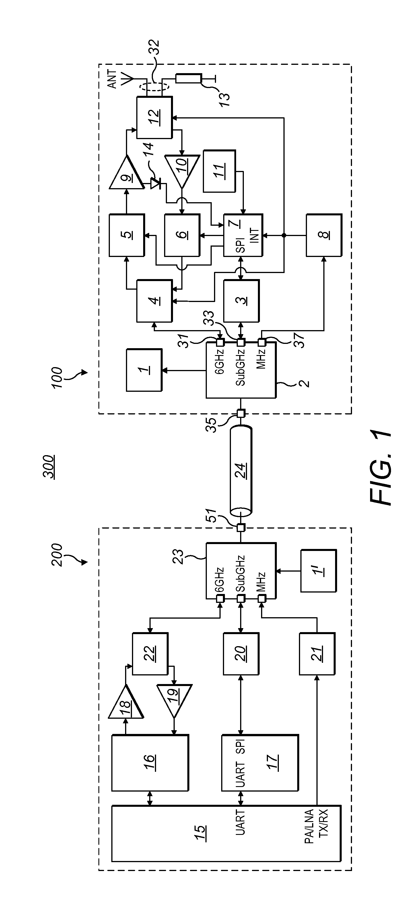
[0013]A compensator module in accordance with an embodiment of the present invention is designed to determine a transmitter output power of the compensator module and to generate therefrom a parameter that represents the transmitter output power. The parameter can be determined from the transmitter output power or from a difference between the transmitter output power and a transmitter power. The compensator module comprises a data interface that is configured to transmit the parameter to the transceiver unit via the antenna cable during operation.

[0014]The invention is based on the fact that, on the one hand, by generating a parameter that represents the transmitter output power and / or the difference between the transmitter output power and the transmitter power, and on the other hand, by transmitting t...


PUM


Abstract

A compensator module (100), which can be connected to a transceiver unit (200) by an antenna cable (24), comprising a signal input (31) configured for supplying a provided transmitter power (SL) in a first frequency band (FB1), which is provided by the transceiver unit (200) to the compensator module (100) as a transmitter input power (ESL), a transmitter amplifier (9) for amplifying the supplied transmitter input power (ESL) to an transmitter output power (ASL), a signal output (32) for delivering the transmitter output power (ASL) in the first frequency band (FB1) to an antenna (ANT) or an equivalent load (13), wherein the compensator module (100) is configured generate a parameter (K) which represents the output transmitter power (ASL), and wherein the compensator module (100) comprises a data interface (33) configured to transmit the parameter (K) to the transceiver unit (200) over the antenna cable (24).

Description

[0001]This application claims priority from German Patent Application No. 10 2014 215 578.9 (DE) filed Aug. 6, 2014 and entitled, “Kompensatormodul für eine Sendeempfängereinheit, Funksystem sowie Verfahren zum Betreiben desselbigen,” the entire contents of which are hereby incorporated by reference.BACKGROUND OF THE INVENTION[0002]The present invention relates to a compensator module that is configured for connection to a transceiver unit by means of an antenna cable, e.g. a coaxial cable. The invention also relates to a radio system comprising a compensator module and a transceiver unit that can be connected to one another via an antenna cable. The invention further relates to a method for operating a radio system comprising a compensator module and a transceiver unit.[0003]Compensator modules that are intended for connection to a transceiver unit by means of an antenna cable are essentially known from the prior art. A compensator module (also referred to as an antenna booster in ...

Claims


Application Information

Patent Timeline
Patent Type & Authority Patents(United States)
IPC IPC(8): H04W24/00H04W52/16H03G3/30H04B1/40H04W52/18H04W24/02
CPCH03G3/3042H04B1/40H04W24/02H04W52/18H04W52/16H03G1/02
Inventor DYKYY, VASYLSHEVCHENKO, IGORKRYZHANSKYI, OLES
Owner U-BLOX
Why Eureka
Try Eureka