Charging support method, management device, and support system for performing wireless charging among plurality of devices
a technology of wireless charging and support system, applied in the direction of battery data exchange, exchanging data charger, transportation and packaging, etc., can solve the problems of high performance of mobile terminals, such as mobile phones, and increase in usage frequency, and achieve the effect of smooth charging
- Summary
- Abstract
- Description
- Claims
- Application Information
AI Technical Summary
Benefits of technology
Problems solved by technology
Method used
Image
Examples
first modification example
(First Modification Example)
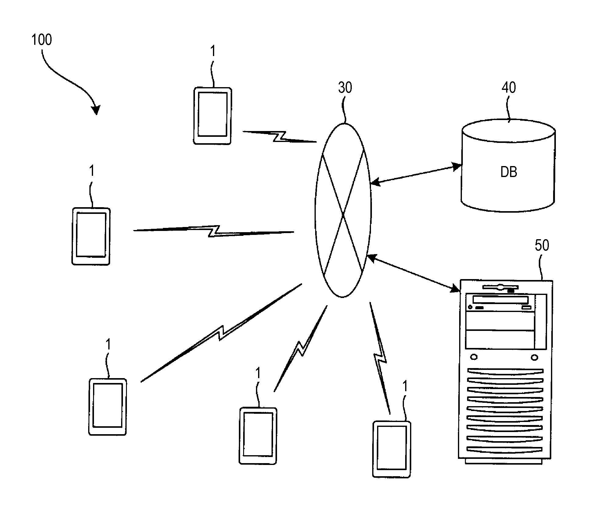
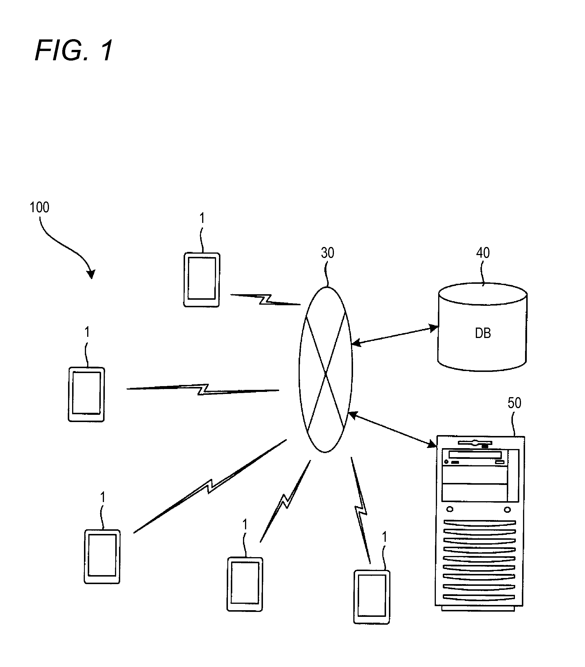
[0084]The purpose of this system resides in that an owner of an electronic apparatus having a power reception function of receiving a power feed from other apparatuses and charging a battery can charge a battery of the host apparatus without needing troublesome work. Accordingly, this system may include at least one electronic apparatus having a power feed function of transmitting power of the battery of the host apparatus to other apparatuses, and at least one electronic apparatus having the power reception function. That is, as shown in FIG. 1, all electronic apparatuses 1 may have the power reception function and the power feed function.
[0085]In regards to an electronic apparatus 1 having only a power reception function, “power feed inhibition” may be recorded as information regarding to power feed permission and inhibition recorded in the database 40 at the time of the installation of the mutual charging program. In regards to an electronic apparatus ...
second modification example
(Second Modification Example)
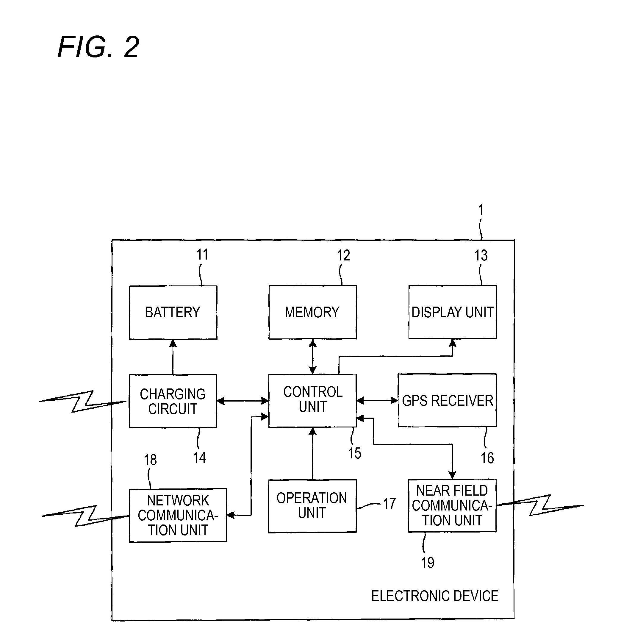
[0086]In the database 40, in addition to information of a movable electronic apparatus 1, information of (charging device ID, positional information, information of power feed permission) of a fixed charging device may be stored in advance. The charging device has a configuration in which the battery 11, the display unit 13, and the GPS receiver 16 in the electronic apparatus 1 are removed, and the charging circuit 14 is configured as a circuit capable of performing a power feed to the electronic apparatus 1.
[0087]When information of the charging device is recorded in the database 40, the management server 50 specifies the power feedable electronic apparatuses 1 including the charging device in the periphery of the power feed-desiring electronic apparatus 1 in Step S2 of FIG. 5 and transmits the positional information and the apparatus IDs of the specified power feedable electronic apparatuses 1 (including the charging device) to the power feed-desiring ...
third modification example
(Third Modification Example)
[0091]As the electronic apparatuses 1 which can participate in this system, in addition to mobile terminals, there are vehicles, such as automobiles, motorcycles, and electric bicycles. The mobile terminals and the vehicles are significantly different in battery capacity width.
[0092]As the power feed-desiring electronic apparatus 1, an apparatus which receives a power feed from a vehicle having large battery capacity and performs stable charging can be used. In case of an automobile or a motorcycle, there are many cases where the automobile or the motorcycle is standing in a parking area, and if the automobile or the motorcycle which is standing is the power feedable electronic apparatus 1, there is a low possibility that the power feedable electronic apparatus 1 moves during charging. Accordingly, it is possible to perform charging without stress.
[0093]In this modification example, a form in which attribute information is included in the apparatus inform...
PUM
 Abstract
Description
Claims
Application Information
 - R&D
- Intellectual Property
- Life Sciences
- Materials
- Tech Scout
- Unparalleled Data Quality
- Higher Quality Content
- 60% Fewer Hallucinations
Browse by: Latest US Patents, China's latest patents, Technical Efficacy Thesaurus, Application Domain, Technology Topic, Popular Technical Reports.
© 2025 PatSnap. All rights reserved.Legal|Privacy policy|Modern Slavery Act Transparency Statement|Sitemap|About US| Contact US: help@patsnap.com


