Power overload protection using hiccup mode
a technology of overload protection and power converter, applied in the direction of electric variable regulation, process and machine control, instruments, etc., can solve the problems of auxiliary transformers being more complex and expensive to install, auxiliary transformers being more expensive to install, and not providing as good regulation as opto-couplers
- Summary
- Abstract
- Description
- Claims
- Application Information
AI Technical Summary
Benefits of technology
Problems solved by technology
Method used
Image
Examples
first preferred embodiment
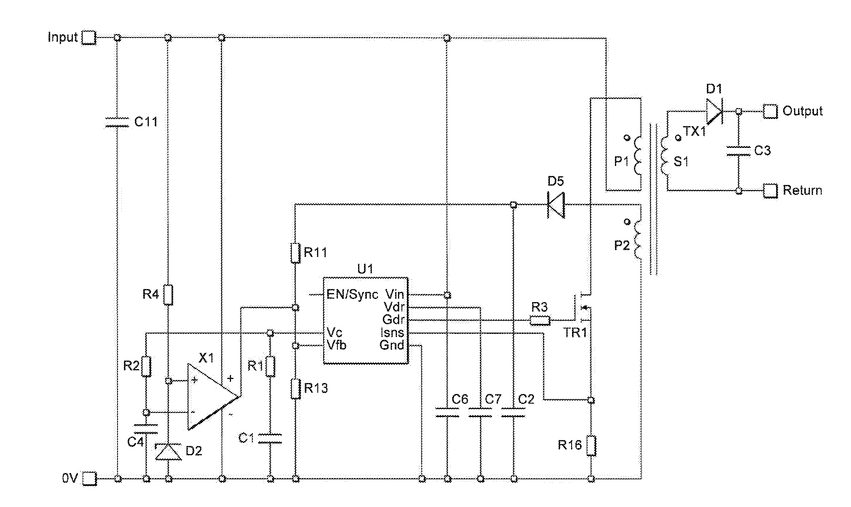
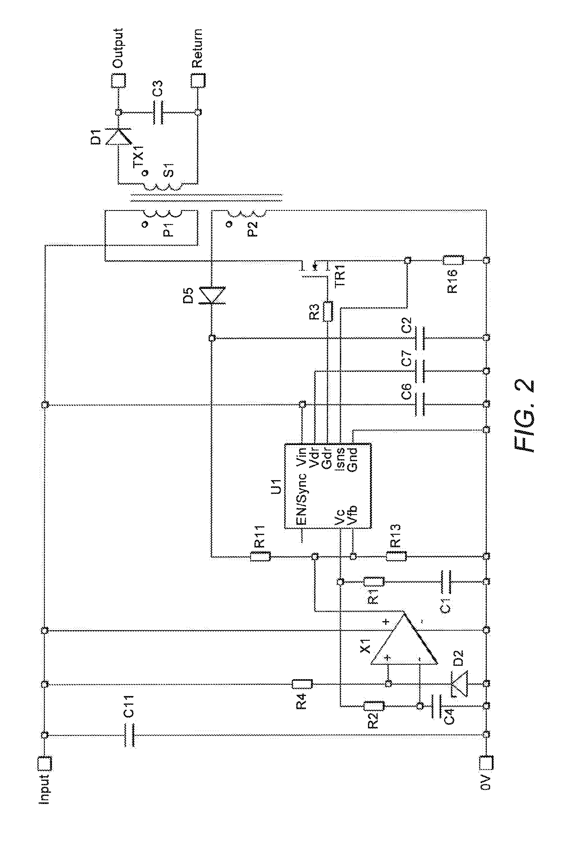
[0038]A first preferred embodiment of the present invention will now be described with reference to FIG. 2.
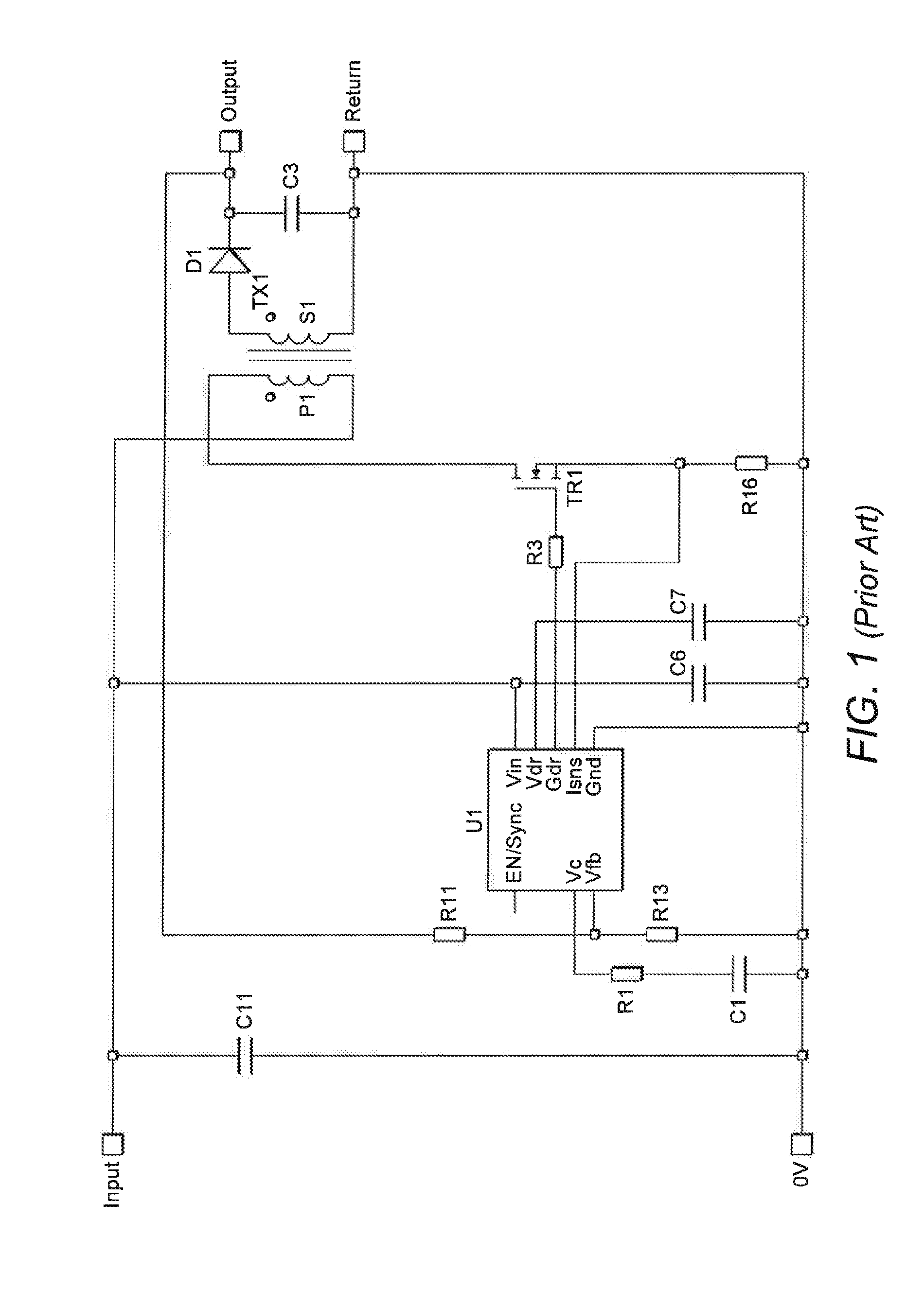
[0039]The circuit in FIG. 2 shows a primary side regulated flyback power supply circuit including auxiliary primary side transformer winding P2. As before, switching circuit is implemented using a switching MOSFET TR1 and a PWM Controller U1. The drain terminal of the MOSFET TR1 connects to one side of the primary transformer winding P1, while the source of MOSFET TR1 connects to the 0 V voltage rail. As is known in the art, the operation of the switching MOSFET TR1 is controlled by signal output from the PWM controller U1. Specifically, the Gate Drive terminal Gdr of the PWM controller U1 is connected to the gate of the switching MOSFET TR1, so that the MOSFET TR1 can be switched on and off as desired to control the energizing of the primary coil P1. The ground terminal Gnd of the PWM controller U1 is connected to the low voltage rail (0 V). The operation of the controller is ...
second preferred embodiment
[0066]A second preferred embodiment of the present invention will now be described with reference to FIG. 4. The components and operation of the circuit is the same as that for the first preferred embodiment. However, in FIG. 4, the comparator X1 and the reference diode D2 and resistor R4 are replaced with an adjustable precision shunt regulator U2. The shunt regulator has an internal 2.5 V reference connected to its comparator non-inverting input.
[0067]The cathode of the shunt regulator is connected to the auxiliary winding P2 via diode D5 and resistor R6. The inverting pin (ref pin) of the shunt regulator U2 is connected to the error amplifier output terminal Vc of PWM controller U1 through resistor R12. As before, the inverting pin is connected to an intermediate point between resistor R12 and capacitor C9 which connects to ground (0 V).
[0068]The output of the internal comparator (its cathode pin) is not connected directly to the voltage feedback pin Vfb of PWM controller U1 beca...
PUM
 Abstract
Description
Claims
Application Information
 - R&D
- Intellectual Property
- Life Sciences
- Materials
- Tech Scout
- Unparalleled Data Quality
- Higher Quality Content
- 60% Fewer Hallucinations
Browse by: Latest US Patents, China's latest patents, Technical Efficacy Thesaurus, Application Domain, Technology Topic, Popular Technical Reports.
© 2025 PatSnap. All rights reserved.Legal|Privacy policy|Modern Slavery Act Transparency Statement|Sitemap|About US| Contact US: help@patsnap.com


