Low impedance radiofrequency shielded window

a radiofrequency shielding and low impedance technology, applied in the field of radiofrequency shielding, can solve the problems of large screen room, high cost, and inability to meet the needs of small business,

Active Publication Date: 2016-11-15
RAMSEY JOHN GORDON
View PDF17 Cites 26 Cited by
  • Summary
  • Abstract
  • Description
  • Claims
  • Application Information

AI Technical Summary

Benefits of technology

[0011]A low impedance radiofrequency shielded window and radiofrequency shielded enclosure that includes the low impedance radiofrequency shielded window is disclosed. The low impedance radiofrequency shielded window comprises a first window layer having a perimeter, a conductive mesh surface and an insulating surface; a first conductive perimeter layer makes ohmic contact with the conductive mesh surface of the first window layer; this conductive perimeter layer extends to enable electrical contact to the enclosure's grounded wall; a second window

Problems solved by technology

Similarly, many sensitive electronic devices may be susceptible to electromagnetic signals in general or radiofrequency signals in particular, and must be shielded from such signals when under test.
A screen room can be quite expensive and therefore may not be economically feasible for a small business.
Likewise, a screen room

Method used


Image

  • Low impedance radiofrequency shielded window
  • Low impedance radiofrequency shielded window
  • Low impedance radiofrequency shielded window

Examples


Embodiment Construction

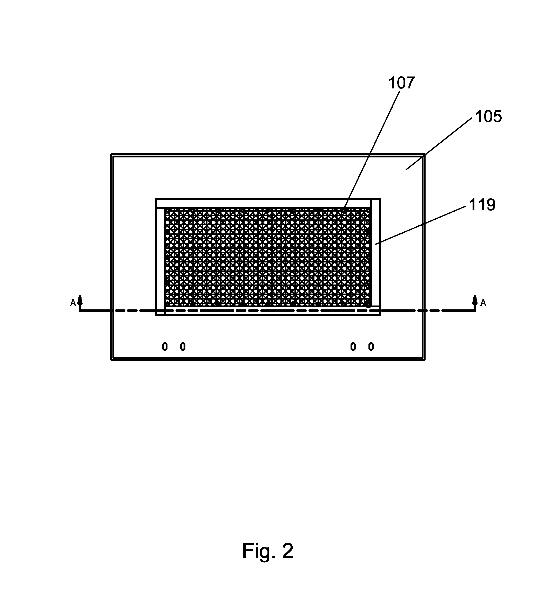
[0022]For a general understanding of the present invention, reference is made to the drawings. In the drawings, like reference numerals have been used throughout to designate identical elements.

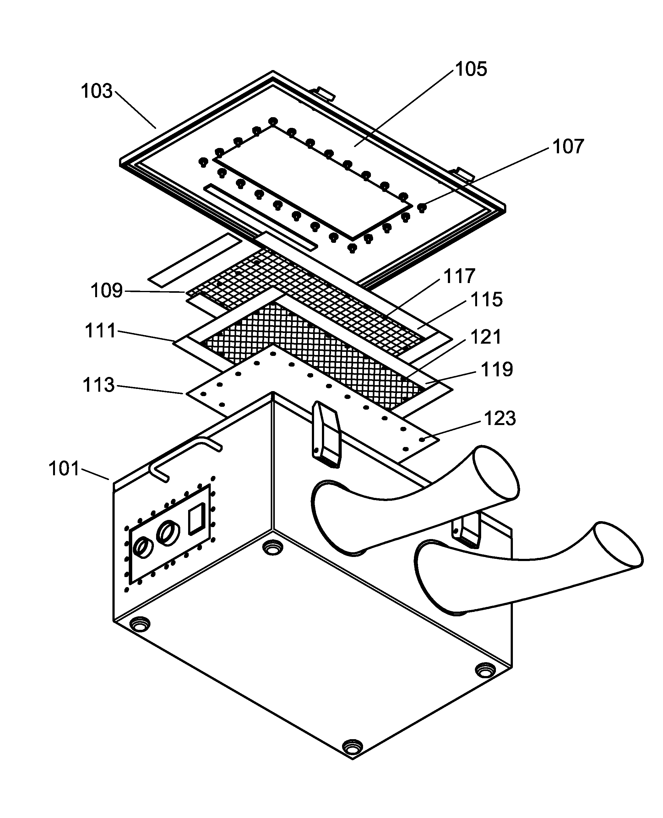
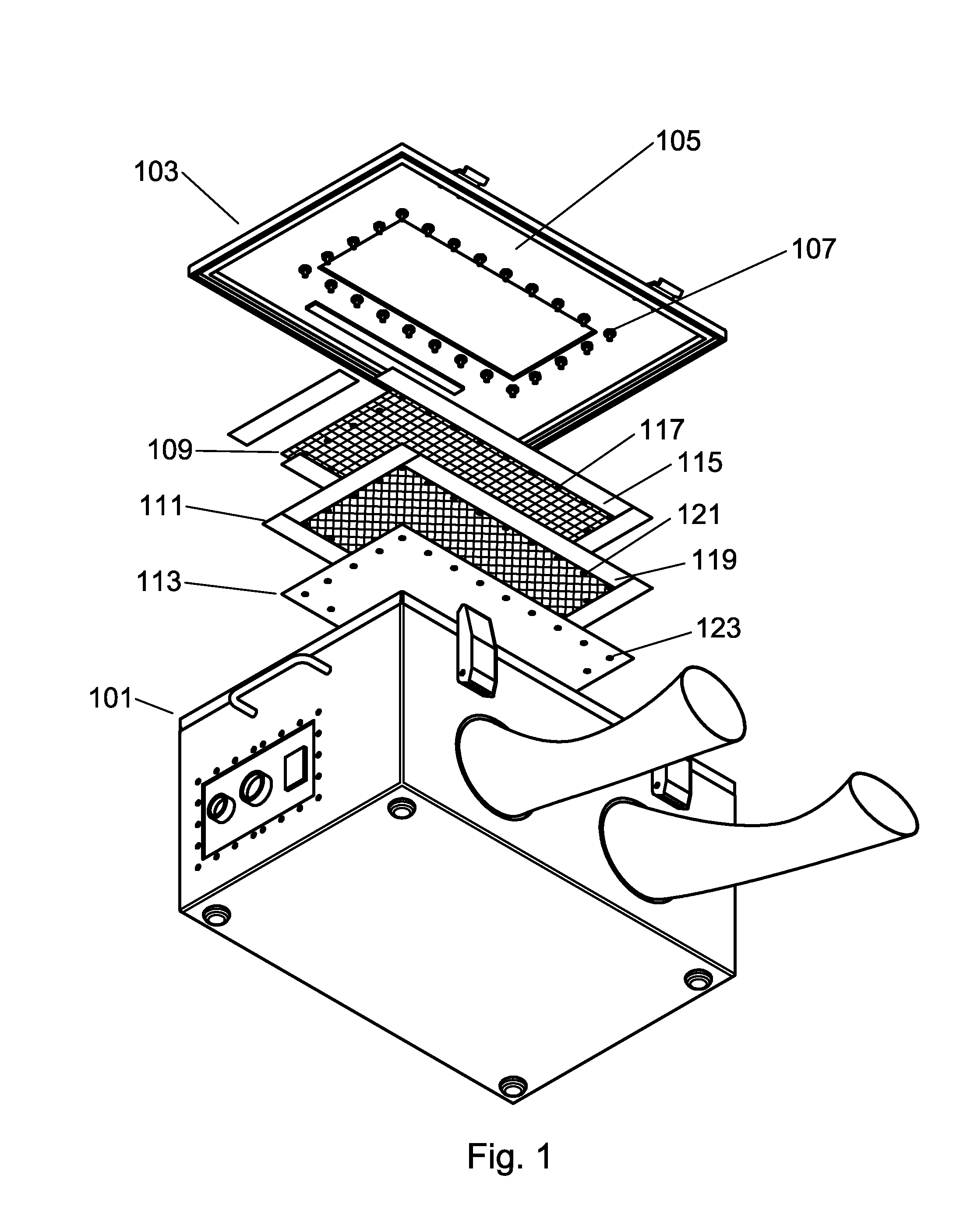
[0023]The low impedance radiofrequency (RF) shielded window is depicted as being installed in an enclosure, however, the radiofrequency shielded window of the present invention may be installed in a variety of enclosures, containers, shelters, buildings, walls, ceilings, cabinets, and the like. While the use of a screen material for radiofrequency shielding in combination with a clear material such as a glass or plastic is known, the specific arrangement of shielded window layers as disclosed herein to achieve low impedance shielding effectiveness has heretofore been unknown.

[0024]Specifically, each layer of screen in a typical radiofrequency shielded window only provides 20-40 db of RF shielding, and thus to achieve greater shielding effectiveness these layers are commonly stacked. With each...


PUM


Abstract

A low impedance radiofrequency shielded window and radiofrequency shielded enclosure that includes the low impedance radiofrequency shielded window is disclosed. Radiofrequency shielded window layers make up the overall window where the layers are configured in parallel such that each window layer has a direct path to ground. By configuring the ground path of the window layers in parallel, overall reactance and hence resistance is reduced, thus increasing shielding effectiveness of the window.

Description

BACKGROUND OF THE INVENTION[0001]1. Field of the Invention[0002]The present invention relates to radiofrequency shielding, and more particularly, relates to a low impedance radiofrequency shielded window.[0003]2. Description of Related Art[0004]The reception and transmission of electromagnetic signals is important to the proper functioning of many devices. Cellular telephones and email devices, notebook computer wireless modems, Global Positioning System receivers, wireless data devices, and the like, all rely on the use of electromagnetic signals in the radiofrequency spectrum to operate. Similarly, many sensitive electronic devices may be susceptible to electromagnetic signals in general or radiofrequency signals in particular, and must be shielded from such signals when under test. Testing, tuning, and repair of such a device can require that the Device Under Test (DUT) be isolated from ambient electromagnetic radiation. Exposing a receiving device to an unambiguous test signal f...

Claims


Application Information

Patent Timeline
IPC IPC(8): H05K9/00
CPCH05K9/0005H05K9/009H05K9/0007H05K9/0088H05K9/0094
Inventor RAMSEY, JOHN GORDON
Owner RAMSEY JOHN GORDON
Why Eureka
Try Eureka