Mechanism for transmitting a rotary movement with variable transmission ratio

a transmission ratio and rotary movement technology, applied in the field of multi-stage gearings, can solve the problems of high chain friction, material fatigue, and higher load on the chain, and achieve the effect of preventing any undesired rotary movemen

Active Publication Date: 2016-11-22
PRAXIS WORKS
View PDF12 Cites 18 Cited by
  • Summary
  • Abstract
  • Description
  • Claims
  • Application Information

AI Technical Summary

Benefits of technology

[0027]In order to prevent the traction means from evading from the side from which the wheel rim sectors are coupled into the plane of the traction means, an edge plate extending in parallel with the plane of alignment will be beneficial. It may advantageously be mounted so as to co-rotate with the wheel set.
[0028]In order to assist the return movement of the wheel rim sectors from the plane of alignment into their resting position, additional spring elements can be of advantage, which are preferably configured as leaf springs. These will cause the reliable return of the wheel rim sectors into a resting position outside the plane of alignment when the associated thrust element assumes its first position.
[0029]Guide elements configured, for instance, as guide pins and / or tilting brackets can be associated to the wheel rim sectors. They will define the substantially axial movement of the wheel rim sectors due to the introduction of force by the respectively associated thrust element, and hence ensure a defined path of the wheel rim sectors during their displacement between an “active position” in the plane of alignment and a “resting position” outside the plane of alignment. These guide elements will, in particular, prevent any undesired rotary movement of the wheel rims about the rotating axle. These guide elements will, as a rule, define the movement of the wheel rim sectors in the sense of a lateral displacement (i.e. in the axial direction), optionally with a small additional radial component, the latter being maintained in parallel with the plane of alignment.

Problems solved by technology

In doing so, disadvantages frequently arise in that the chain is moved out of alignment, which will cause a higher friction in the chain, or a higher load on the chain, thus resulting in material fatigue.
A further disadvantage consists in that the chain is partially present on two chain blades during the shifting procedure, which is why no power can be transmitted during that time.
In addition, vibrations may cause the chain to skip to adjacent chain blades, which will again cause problems during load operation.
Another disadvantage is that the derailleurs are usually located on exposed sites, as is frequently the case particularly in bicycles, and are therefore prone to damage during cross-country rides, e.g. by bushes.
Due to the plurality of axially adjacently arranged chain blades, derailleur gears also require relatively much space, which will again prevent a gearshift having the full range of transmission ratios from being realized on the crankshaft, which is better protected, yet very limited in terms of space.
The drawback in that case is the high weight that such sprocket gears have, and the high constructive and economic expenditures.
This principle is only suitable for frictionally engaged, but not for positively engaged traction media such as chains or toothed belts.
This involves the disadvantage of a constant contact, and hence friction, persisting during the operation of the system.
In addition to an undesired load and wear, this will also lead to the generation of noise.
This renders such principles uncomfortable in practice and does not constitute a viable solution.
Since every sprocket sector has to be mounted on two or more pins, the latter will tend to jamming if only one pin is actuated, and render impossible any movement of the toothed sectors.
The guidance and meshing of three pins per sector, however, involves the disadvantage that an excursion of a sector is not possible without inacceptable expenditures.
Another problem relates to how the individual sectors are to maintain their positions in or out of engagement after having left the stationary guide carriage.
In this respect, none of the known solutions offers an approach that is effective in practice.
However, what is disadvantageous is the relatively high space demand, since the individual sectors have to be pivoted out at relatively large angles in order to completely leave the region of the running chain.
In addition, this solution involves the drawback of the force for a gear change having to be introduced by contacts between stationary and rotating parts.
This will again cause the already mentioned friction and noise generation.

Method used


Image

  • Mechanism for transmitting a rotary movement with variable transmission ratio
  • Mechanism for transmitting a rotary movement with variable transmission ratio
  • Mechanism for transmitting a rotary movement with variable transmission ratio

Examples


Embodiment Construction

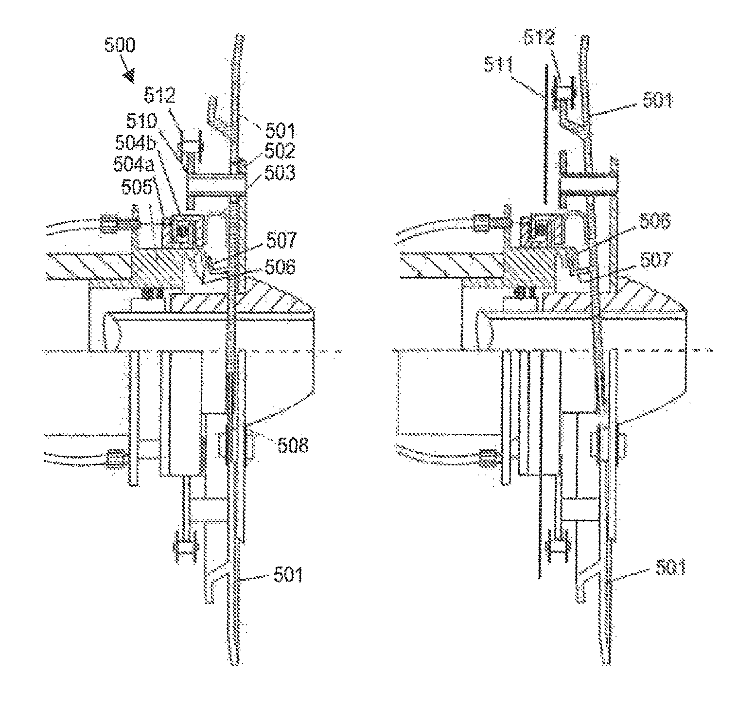
[0073]A first aspect of the invention avoids contact, as far as possible, between stationary and rotating units in that the mechanism effecting the displacement of the sectored, divided or interrupted sprockets is in constant engagement with the rotating unit in a rotationally decoupled manner. According to the invention, this rotationally decoupled control mechanism is made possible in that the stationary part of the mechanism is configured to be rotationally decoupled relative to the rotating part by double mounting. This type of operation overcomes the drawback of known solutions comprising the repeatedly occurring contact between rotating parts and the relatively stationary part.

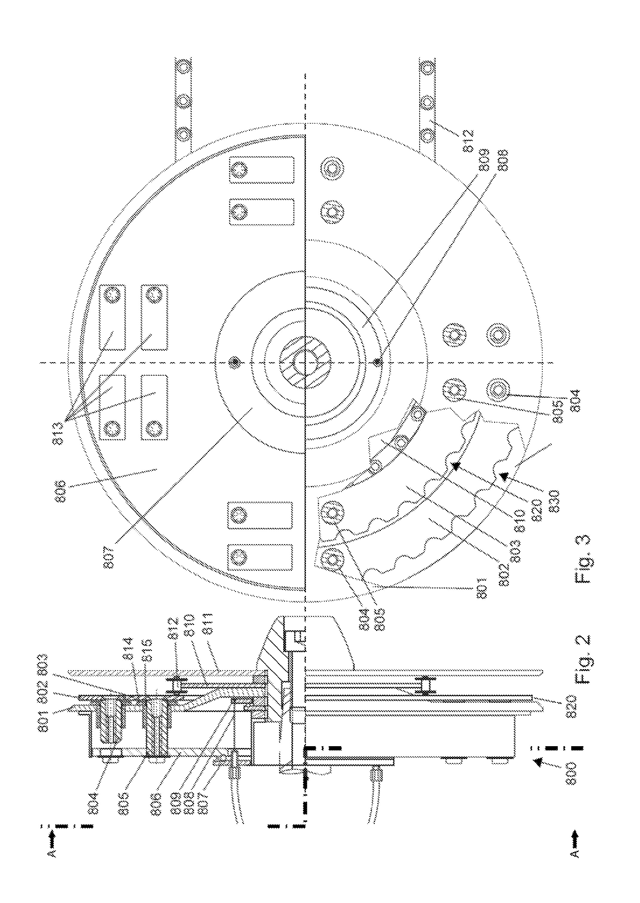
[0074]In the following, this will be demonstrated by way of an example, which is illustrated in FIGS. 2 to 7 and constitutes an embodiment of a simplified gearing according to the invention comprising three gears and the associated control mechanism 800.

[0075]FIG. 2 is a front view of the gearing, i.e. v...


PUM


Abstract

A control mechanism (800) for setting a transmission ratio between a traction means (812), in particular chain, and a wheel set that is rotatable about a wheel axle and includes two or more wheel blades (810, 820, 830), in particular sprocket blades, adjusts the wheel rim sectors relative to a fixed plane of the traction means in a direction transverse to the plane of alignment. At least one of the wheel blades is composed of a plurality of independently adjustable wheel rim sectors (802, 803). By means of a control component (807) mounted decoupled from a rotary movement of the wheel set, a plurality of co-rotating thrust elements (804, 805) are each displaced via rotation-free couplings between a first and a second position at least in the axial direction, wherein each of the wheel rim sectors is connected in a rotationally fixed manner to a respectively associated thrust element. The first position of a thrust element corresponds to the position of the associated wheel rim sector outside the plane of alignment, whereas a thrust element located in the second position exerts on the respective wheel rim sector, at least as long the latter is outside the plane of the traction means, a force for displacing the respective wheel rim sector into the plane of alignment, thus shifting the same into the plane.

Description

CROSS-REFERENCE TO RELATED APPLICATIONS[0001]This Application is a U.S. National Stage Application filed under 35 U.S.C. §371 of International Application PCT / AT2012 / 050109, filed Jul. 18, 2012, designating the United States, which claims priority from Austrian Patent Application A 1100 / 2011, filed Jul. 27, 2011, the complete disclosures of which are hereby incorporated herein by reference in their entirety for all purposes.FIELD OF THE INVENTION AND TECHNOLOGICAL BACKGROUND[0002]The invention relates to the field of multistage gearings used for power transmission by continuous, articulated or flexible traction-transmitting means such as a belt or a chain. More particularly, the invention is directed to a control mechanism for setting a transmission ratio between a traction means, e.g. a chain or a belt, and a wheel set that is rotatable about a wheel axle and includes two or more wheel blades. A selected one of the wheel blades is wrapped around by the traction means; at least one ...

Claims


Application Information

Patent Timeline
Patent Type & Authority Patents(United States)
IPC IPC(8): B62M9/14B62M9/10B62M9/08B62M9/06
CPCB62M9/14B62M9/06B62M9/08B62M9/10B62M9/105
Inventor SCHUSTER, GREGOR
Owner PRAXIS WORKS
Why Eureka
Try Eureka