
Method and apparatus for controlling an engine to achieve a boosted performance for a limited time

a technology of limited time and engine, applied in the direction of electric control, speed sensing governor, machines/engines, etc., can solve the problems of increasing the excess availability limit, limiting the maximum road speed limit, etc., to achieve the effect of maintaining torque, boosting vehicle speed, and increasing engine speed

Active Publication Date: 2016-11-22
VOLVO LASTVAGNAR AB
View PDF17 Cites 0 Cited by
  • Summary
  • Abstract
  • Description
  • Claims
  • Application Information

AI Technical Summary

Benefits of technology

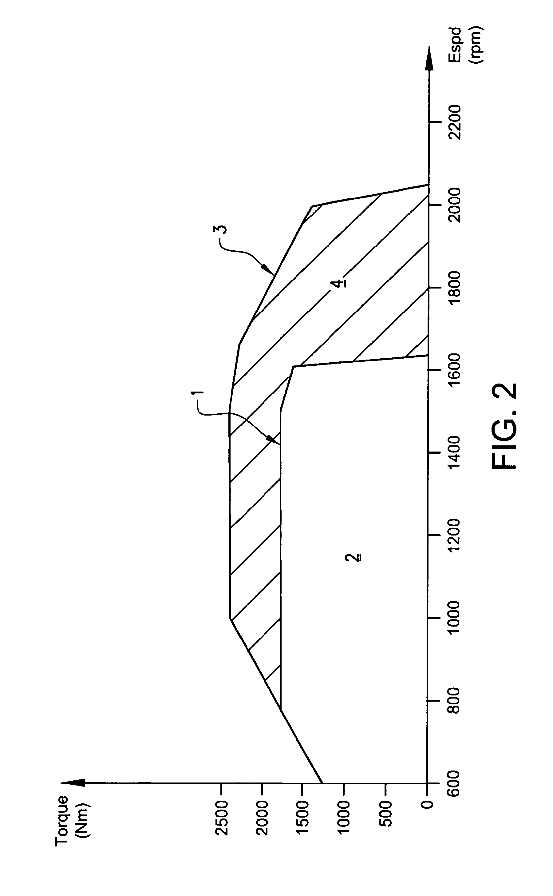
This patent describes a method for controlling the torque and engine speed of an automobile engine, rather than the vehicle speed. By controlling torque, the engine can maintain a higher speed even when driving uphill, which improves driver comfort. The excess torque can be saved for later use by setting a limit on the amount of excess torque available to the driver. The base and excess torque verses engine speed curve can be dynamically determined based on the road profile and driver input. The use of a dynamic excess availability limit encourages the driver to save access time to the excess working range, while the driver input for requesting access to the excess working range is conveniently performed through a dedicated throttle function. Overall, this method improves the overall perception of using the excess working range for the driver.

Problems solved by technology

However, in certain driving situations, it may be a disadvantage to be limited to the maximum road speed limit, such as during an overtaking or passing of another vehicle.
Continued driving without using the excess working range will not increase the excess availability limit.

Method used


Image

  • Method and apparatus for controlling an engine to achieve a boosted performance for a limited time
  • Method and apparatus for controlling an engine to achieve a boosted performance for a limited time
  • Method and apparatus for controlling an engine to achieve a boosted performance for a limited time

Examples


Embodiment Construction

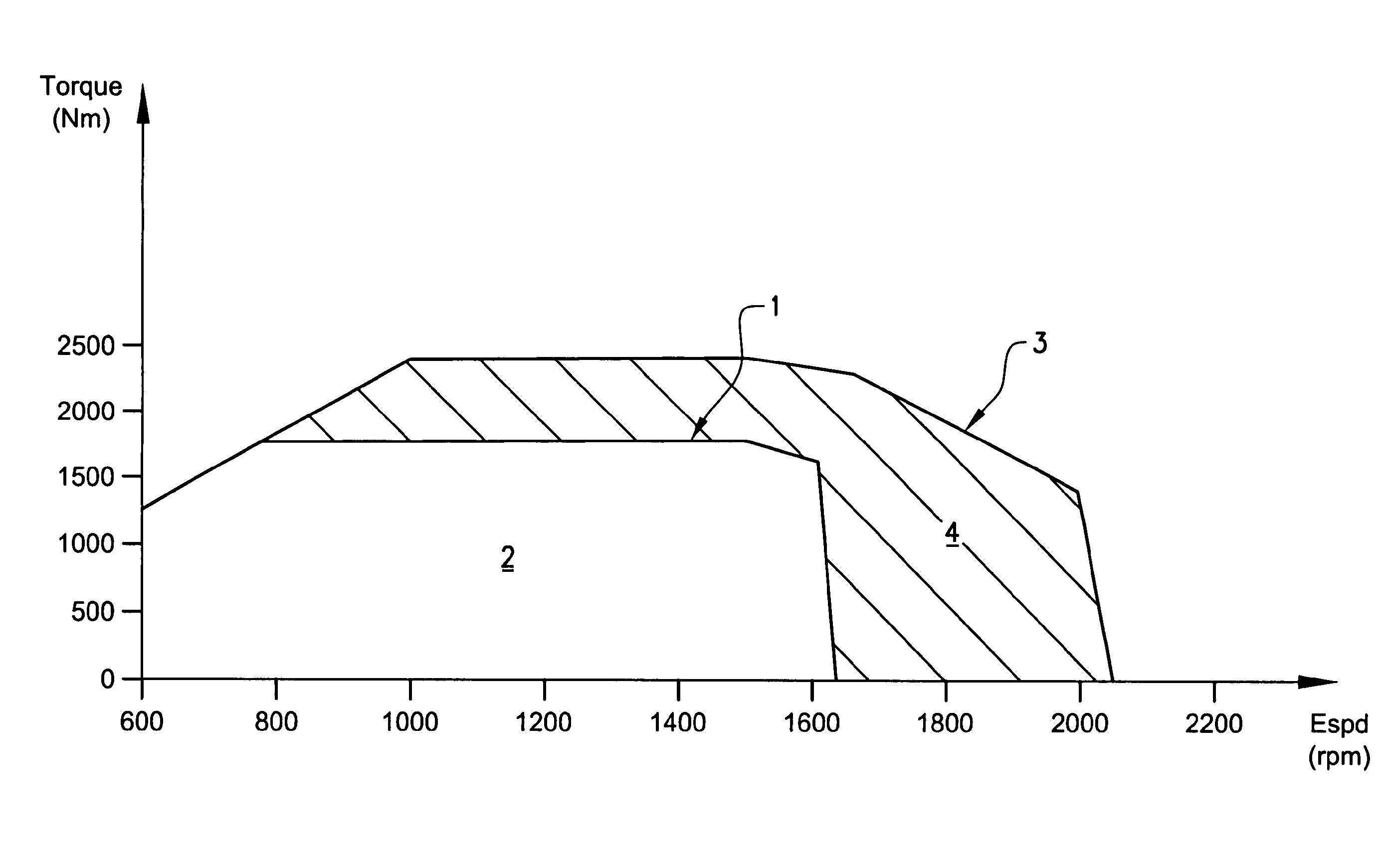
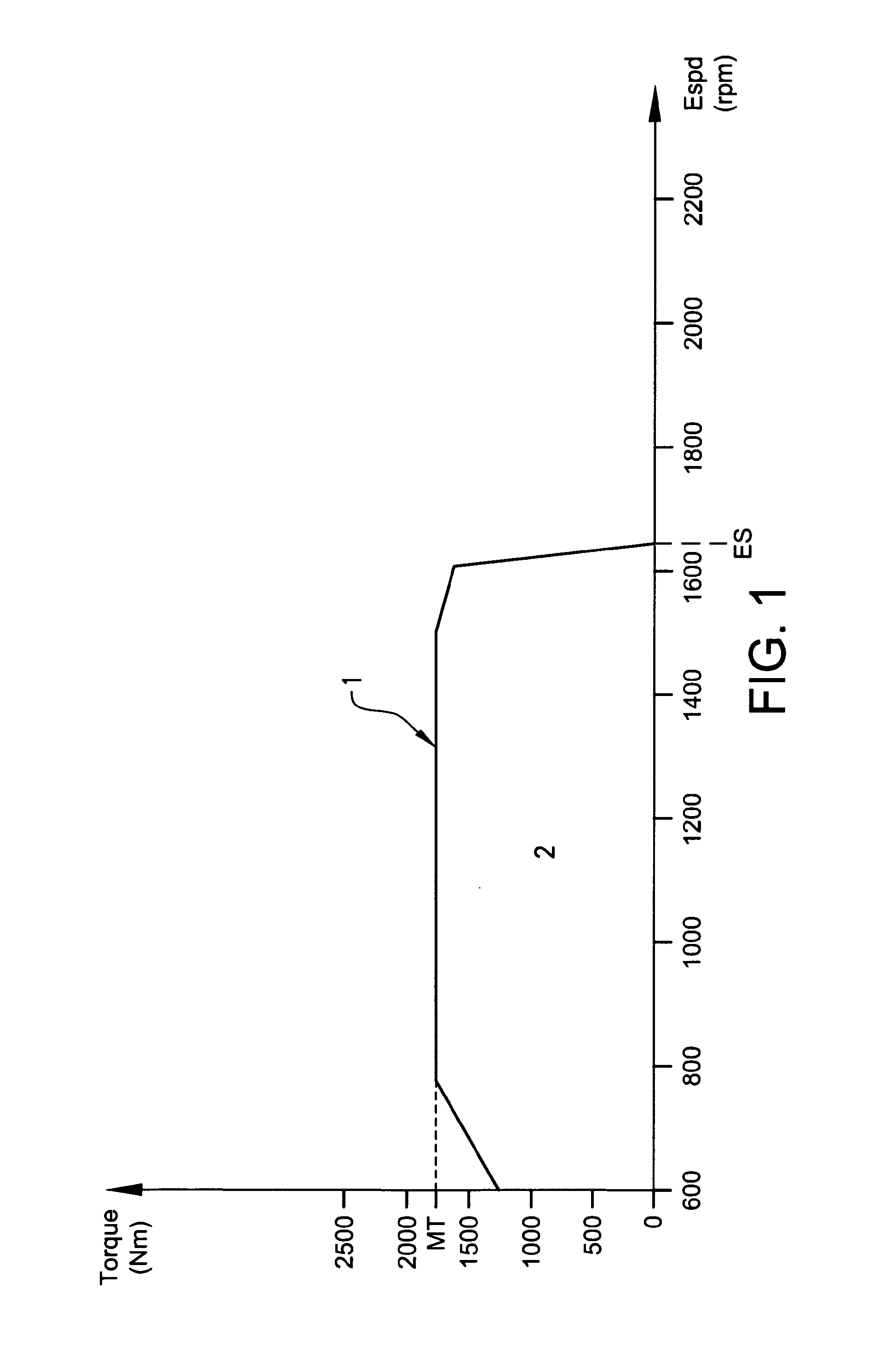
[0080]FIG. 1 is a diagram illustrating an example of a torque versus engine speed curve 1 for an engine of a heavy vehicle. It will be understood that the illustrated curve is an example only and that innumerous variants of torque versus engine speed curves are possible within the frame of this invention.

[0081]The torque versus engine speed curve defines a maximum torque level (MT) (about 1750 Nm in FIG. 1). Generally, in the context of heavy vehicle engines, the maximum torque level will be reached at a fairly low engine speed (800 rpm in FIG. 1). At increasing engine speeds, the curve will maintain the maximum torque level (MT) for a relatively broad range (until about 1500 rpm in FIG. 1). Thereafter, the curve will slope downwards until the torque reaches zero. The engine speed at which the torque is zero is referred to at the end engine speed (ES) (just above 1600 rpm in FIG. 1).

[0082]The engine may work in a base working range 2 being defined by the area underneath the base tor...


PUM


Abstract

A method is provided for controlling an engine to allow a driver to obtain a working range of the engine in excess a base working range thereof The method includes establishing a base working range, which limits are defined by a base torque versus engine speed curve, establishing an excess working range, which limits are defined between the base torque versus engine speed curve and an excess torque versus engine speed curve, the excess torque versus engine speed curve displaying a higher maximum torque level and / or a higher end engine speed as compared to the base torque versus engine speed curve, establishing an excess availability limit, defining the maximum duration or maximum distance of access to the excess working range per unit time or unit distance, calculating a cumulative consumed excess value per unit time or unit distance by summating any time periods or distances during which the excess working range is accessed within the unit time or unit distance, and controlling the engine in response to driver input to allow access to the excess working range only when the cumulative consumed excess value is less than the excess availability limit.

Description

BACKGROUND AND SUMMARY[0001]This application relates to a method for controlling an engine to allow a driver to obtain a working range of the engine in excess of a base working range thereof. In another aspect, the application relates to a system for controlling an engine to allow a driver to obtain a working range of the engine in excess of a base working range thereof. The engine is preferably an engine for a heavy vehicle, such as a lorry or truck.[0002]Fuel economy is an increasingly important subject to the world's fleets of heavy vehicles, motivated both by economy and by environmental concerns. In order to delimit the fuel consumption during transports with heavy vehicles, it has been suggested to control the driving patterns of the drivers of the vehicles.[0003]For example, it is common practice to set a maximum road speed limit (RSL) for a fleet of vehicles, which maximum road speed limit cannot be exceeded by the driver of the vehicle. Generally, only the manager of the ve...

Claims


Application Information

Patent Timeline
Patent Type & Authority Patents(United States)
IPC IPC(8): F02D41/00F02D31/00F02D11/10F02D41/02
CPCF02D31/001F02D11/105F02D41/021F02D2250/26
Inventor ERIKSSON, JOHNNY
Owner VOLVO LASTVAGNAR AB
Learn More