Stud locking device

a locking device and stud technology, applied in the direction of screws, threaded fasteners, bolts, etc., can solve the problems of difficult guiding and inserting the stud with respect to the stud-receiving hole, affecting the stud's insertion accuracy, so as to facilitate the tip guiding, avoid wobbling, and facilitate the effect of insertion

Active Publication Date: 2016-11-22
NEWFREY
View PDF22 Cites 3 Cited by
  • Summary
  • Abstract
  • Description
  • Claims
  • Application Information

AI Technical Summary

Benefits of technology

[0012]It is therefore an object of the present invention to provide a stud locking device capable of mounting a target member such as an undercover to a support member such as a panel of an automotive vehicle, readily and reliably. It is another object of the present invention to provide a stud locking device capable of readily ascertaining whether a clip is perfectly mounted to a stud.

Problems solved by technology

The hexagonal hole has a relatively small diameter and a relatively long length so as to ensure engagement with the hexagonal wrench, and thus it is difficult to visually ascertain how much the first clip is inserted with respect to the stud, even when viewed from above the hexagonal hole.
If the first clip is not fully inserted, a pull-out load is likely to decrease.
Thus, when the stud is inserted into the stud-receiving hole, it is likely that there is difficulty in guiding and inserting the stud with respect to the stud-receiving hole.
Thus, the stud bolt clip is likely to fail to be reliable mounted.
Thus, it is necessary to form, in the target member, a mounting hole together with the pair of quadrangular-shaped member through-grooves, i.e., take a lot of time and effort for processing of the target member.

Method used


Image

  • Stud locking device
  • Stud locking device
  • Stud locking device

Examples


Embodiment Construction

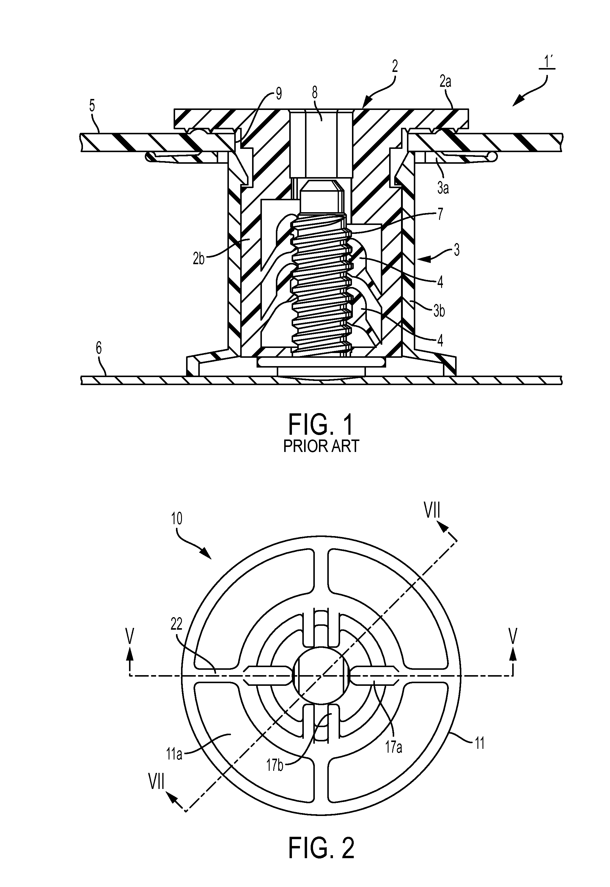
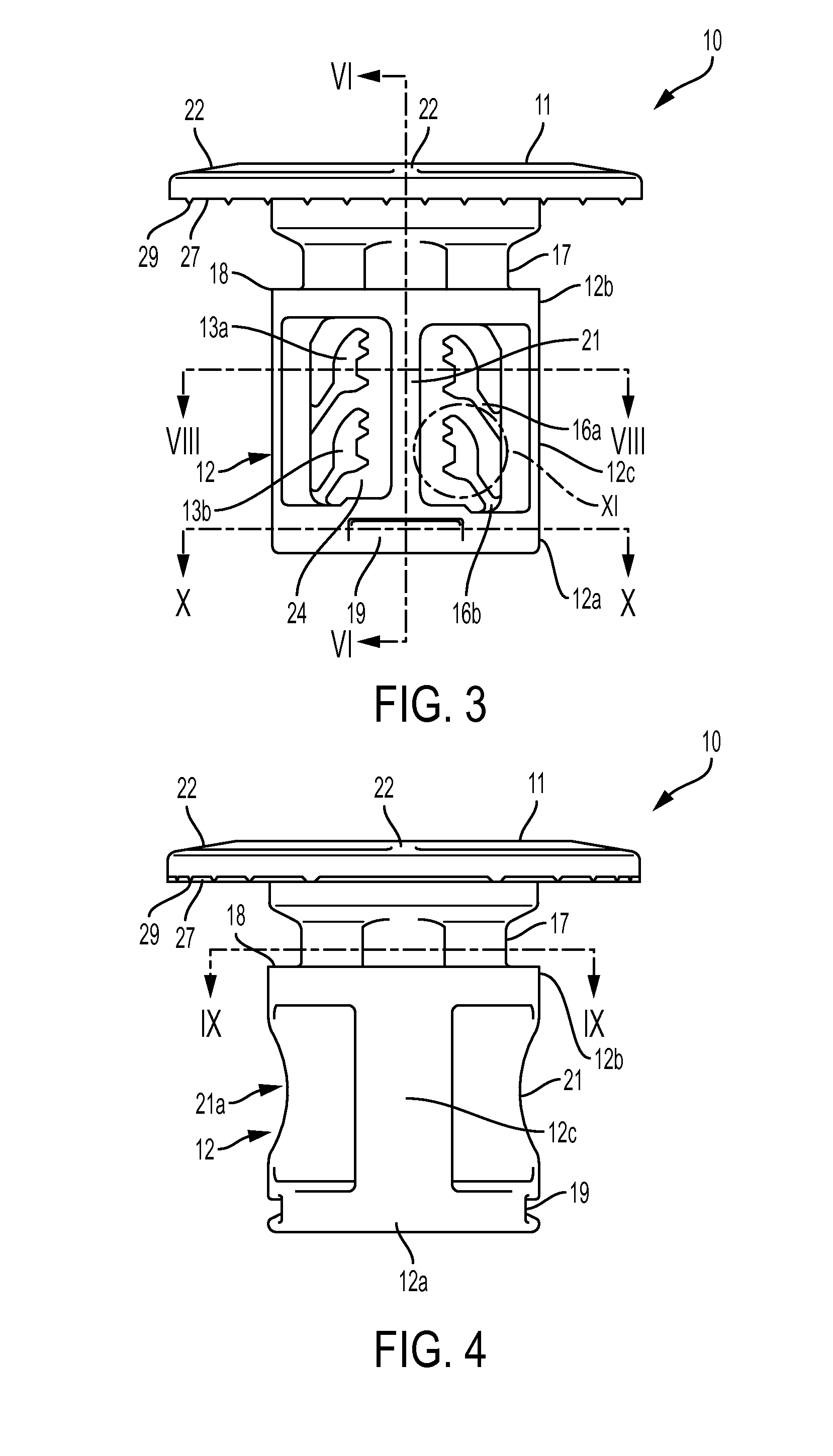
[0049]With reference to the drawings, the present invention will now be described based on an embodiment thereof. A stud locking device 1 according to a first embodiment of the present invention comprises a first clip 10 illustrated in FIGS. 2 to 11, which is made of a hard synthetic resin and molded as a single piece, and a second clip 30 illustrated in FIGS. 12 to 20, which is made of a hard synthetic resin and molded as a single piece.

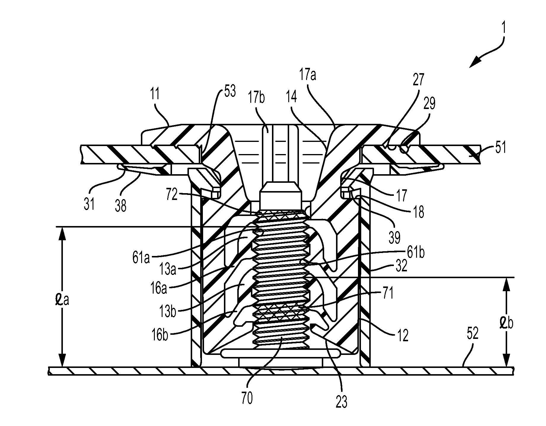
[0050]Before describing each configuration of the first clip 10 and the second clip 30, an outline of a configuration of the stud locking device 1 will be described. FIG. 21 is a sectional view illustrating a state in which a target member 51 is mounted to a support member 52 with a stud 70 by using the stud locking device 1 according to the first embodiment of the present invention. The first clip 10 and the second clip 30 of the stud locking device 1 are coupled together while clamping a sheet-shaped target member 51 such as an undercover therebet...


PUM


Abstract

A stud locking device, which in an assembled condition can hold a target member to a support member, the target member defining a through hole, and the support member including an axially projecting stud; the stud locking device comprising: a first clip including an inner cylindrical portion with a first flange at a target end and defining a central bore for receiving the stud, and insertable at a base end through the mounting hole; and a second clip including: a outer cylindrical portion capable of receiving coaxially the first cylindrical portion; and a second flange provided at a target end of the outer cylindrical portion; and wherein a tapered bore is defined by and coaxial with the first flange and first cylindrical portion, the tapered bore open in the upper surface of the flange, narrowing with increasing axial distance from the open end, and connected to the central bore.

Description

CROSS-REFERENCE TO RELATED APPLICATIONS[0001]This application is a continuation of PCT / JP2013 / 71691, filed on Aug. 9, 2013, which claims priority from Japanese Patent Application No. 2012-180019, filed on Aug. 15, 2012, the disclosure of which is incorporated herein by reference.BACKGROUND OF THE INVENTION[0002]The present invention relates to a locking device usable for mounting a sheet-shaped target member (e.g., an undercover) to a support member (e.g., a panel of an automotive vehicle) having a stud (e.g., a threaded stud) fixed thereto. More specifically, it relates to a stud locking device usable for mounting the target member to the support member, in such a manner that it is lockedly engaged with the stud while retaining the target member.[0003]Generally, a locking device is employed as a means to mount a sheet-shaped target member such as an undercover to a support member such as a panel of an automotive vehicle. In advance of an operation of mounting a wide sheet-shaped ta...

Claims


Application Information

Patent Timeline
Patent Type & Authority Patents(United States)
IPC IPC(8): F16B37/08F16B39/28B60R13/02
CPCF16B39/28B60R13/0206F16B37/0842F16B37/0857B62D25/20F16B21/06F16B37/08
Inventor AOSHIMA, YUUKI
Owner NEWFREY
Why Eureka
Try Eureka