Gas turbine engine components having sealed stress relief slots and methods for the fabrication thereof

a technology of stress relief slots and gas turbine engines, which is applied in the direction of manufacturing tools, machines/engines, stators, etc., can solve the problems of increasing the volume of airflow required for cooling purposes, affecting the efficiency of gas turbine engines, and unplanned leakage across the turbine nozzle, so as to achieve the effect of reducing thermomechanical stress

Active Publication Date: 2016-11-29
HONEYWELL INT INC
View PDF15 Cites 2 Cited by
  • Summary
  • Abstract
  • Description
  • Claims
  • Application Information

AI Technical Summary

Benefits of technology

[0007]Further provided are embodiments of a gas turbine engine component, such as a turbine nozzle or combustor liner. In one embodiment, the gas turbine engine component includes a component body having a radially-extending wall projecting therefrom. The component body and the radially-extending wall are exposed to a core gas flow path and to a secondary cooling flow path, respectively, when the gas turbine engine component is installed within the gas turbine engine. A plurality of stress relief slots extends axially through the radially-extending wall. A high temperature sealing material plugs or fills the plurality of stress relief slots and impedes leakage across the radially-extending wall. The high temperature sealing material cracks or factures to alleviate thermomechanical stress when a temperature differential develops across the radially-extending wall during usage of the component.

Problems solved by technology

In certain cases, undesired leakage can occur across the turbine nozzle interface between the outer cooling flow path and the core gas flow path.
Such leakage can negatively affect the efficiency of the gas turbine engine, especially when smaller in size, and may increase the volume of airflow required for cooling purposes.
Temperature limitations may require that such compression seals are radially offset from the core gas flow path by a certain distance to reduce the operational temperatures to which the seals are exposed.
Unfortunately, this also has the effect of increasing temperature differentials that develop across the radially-elongated rails during engine operation, which may result in excessively high hoop stresses within the rails thereby hastening Thermomechanical Fatigue (TMF) and reducing the service lifespan of the turbine nozzle.
The inclusion of stress relief slots in the nozzle rail may, however, permit an undesirably large amount of leakage across the turbine nozzle mounting interfaces thereby defeating the purpose of the compression seals or at least diminishing the effectiveness thereof.

Method used


Image

  • Gas turbine engine components having sealed stress relief slots and methods for the fabrication thereof
  • Gas turbine engine components having sealed stress relief slots and methods for the fabrication thereof
  • Gas turbine engine components having sealed stress relief slots and methods for the fabrication thereof

Examples


Embodiment Construction

[0015]The following Detailed Description is merely exemplary in nature and is not intended to limit the invention or the application and uses of the invention. Furthermore, there is no intention to be bound by any theory presented in the preceding Background or the following Detailed Description. Terms such as “comprise,”“include,”“have,” and variations thereof are utilized herein to denote non-exclusive inclusions. Such terms may thus be utilized in describing processes, articles, apparatuses, and the like that include one or more named steps or elements, but may further include additional unnamed steps or elements.

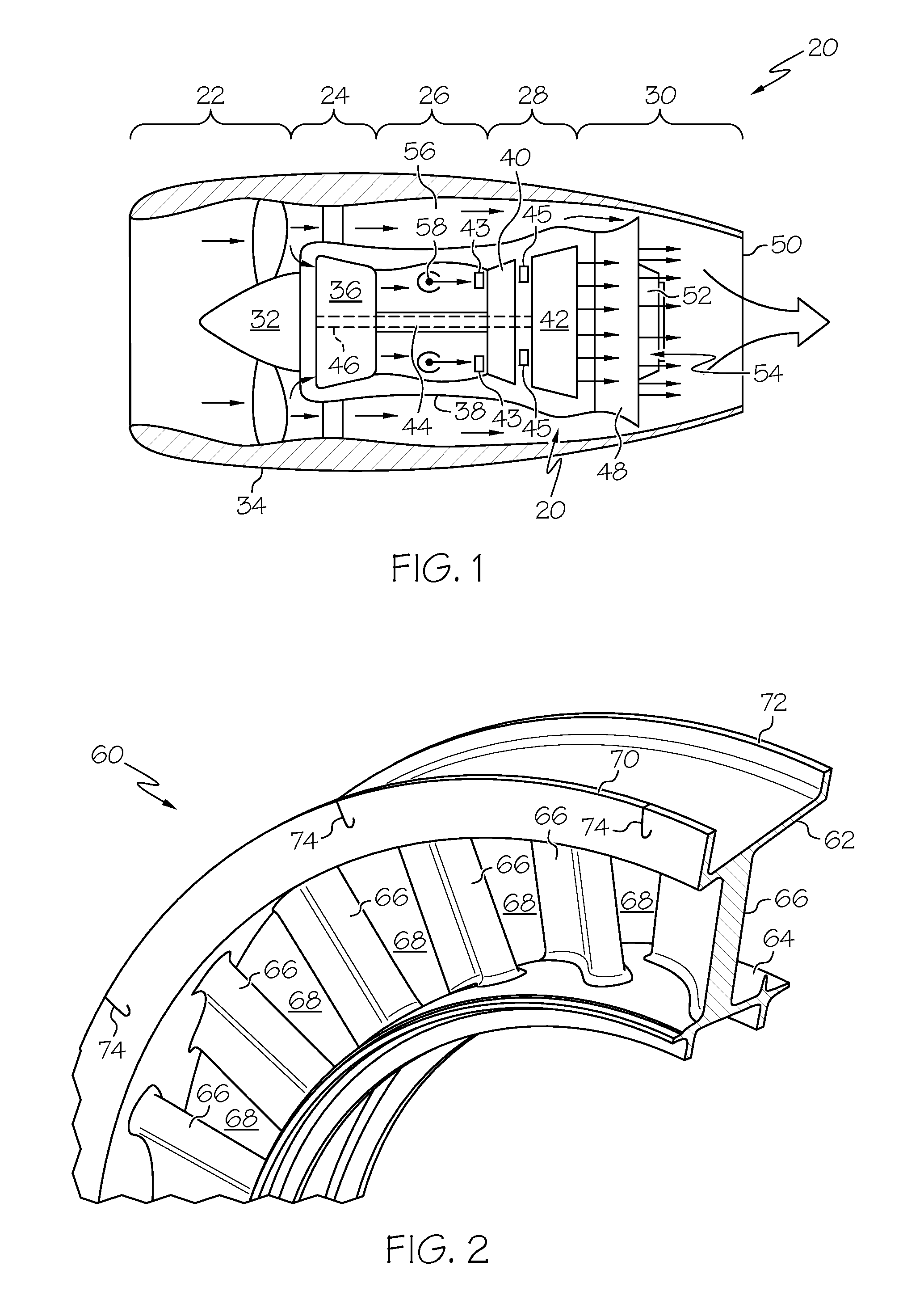
[0016]FIG. 1 is a simplified cross-sectional view of a gas turbine engine (GTE) 20 illustrated in accordance with an exemplary embodiment of the present invention. By way example, GTE 20 is illustrated in FIG. 1 as a two spool turbofan engine including an intake section 22, a compressor section 24, a combustion section 26, a turbine section 28, and an exhaust section 30....


PUM

PropertyMeasurementUnit
widthaaaaaaaaaa
widthaaaaaaaaaa
stressaaaaaaaaaa

Abstract

Embodiments of a gas turbine engine component having sealed stress relief slots are provided, as are embodiments of a gas turbine engine containing such a component and embodiments of a method for fabricating such a component. In one embodiment, the gas turbine engine includes a core gas flow path, a secondary cooling flow path, and a turbine nozzle or other gas turbine engine component. The component includes, in turn, a component body through which the core gas flow path extends, a radially-extending wall projecting from the component body and into the secondary cooling flow path, and one or more stress relief slots formed in the radially-extending wall. The stress relief slots are filled with a high temperature sealing material, which impedes leakage between the second cooling and core gas flow paths and which fractures to alleviate thermomechanical stress within the radially-extending wall during operation of the gas turbine engine.

Description

STATEMENT REGARDING FEDERALLY-SPONSORED RESEARCH OR DEVELOPMENT[0001]This invention was made with Government support under W911W6-08-2-0001 awarded the U.S. Army (AATE Program). The Government has certain rights in the invention.TECHNICAL FIELD[0002]The following disclosure relates generally to gas turbine engines and, more particularly, to turbine nozzles and other gas turbine engine components having stress relief slots filled with high temperature sealing material, as well as to methods for fabricating gas turbine engine components having sealed stress relief slots.BACKGROUND[0003]Gas turbine engines are commonly produced to include turbine nozzles, which accelerate and turn combustive gas flow toward the blades of a turbine rotor downstream of the nozzle. The turbine nozzle may have a generally annular or ring-shaped body including an inner endwall, an outer endwall circumscribing the inner endwall, and a series of circumferentially-spaced vanes extending between the inner and o...

Claims


Application Information

Patent Timeline
Patent Type & Authority Patents(United States)
IPC IPC(8): F01D11/00B23D19/00F01D9/04F01D1/06F01D25/12B22D25/02B22D25/06B22D19/00
CPCF01D11/005B22D19/00B22D25/02B22D25/06F01D1/06F01D9/041F01D25/12F05D2220/32F05D2230/30F05D2240/55F05D2260/20F05D2260/941
Inventor SMOKE, JASONTUCKER, BRADLEY REEDRIAHI, ARDESHIRZURMEHLY, EDMIRZAMOGHADAM, ALEXANDER
Owner HONEYWELL INT INC
Why Eureka
Try Eureka