Turbine blade

a turbine blade and blade technology, applied in the field of turbine blades, can solve the problems that the reduction of wall thickness can have a negative effect on the service life of the turbine blade, and achieve the effect of reducing thermomechanical stresses

Active Publication Date: 2018-07-05
SIEMENS ENERGY GLOBAL GMBH & CO KG
View PDF2 Cites 4 Cited by
  • Summary
  • Abstract
  • Description
  • Claims
  • Application Information

AI Technical Summary

Benefits of technology

[0012]Such a turbine blade can be cooled particularly homogeneously, thereby reducing thermomechanical stresses in the material of the turbine blade.

Problems solved by technology

The reduced wall thickness can have a negative effect on the service life of the turbine blade for strength reasons, however, this being undesired.

Method used


Image

  • Turbine blade
  • Turbine blade
  • Turbine blade

Examples


Embodiment Construction

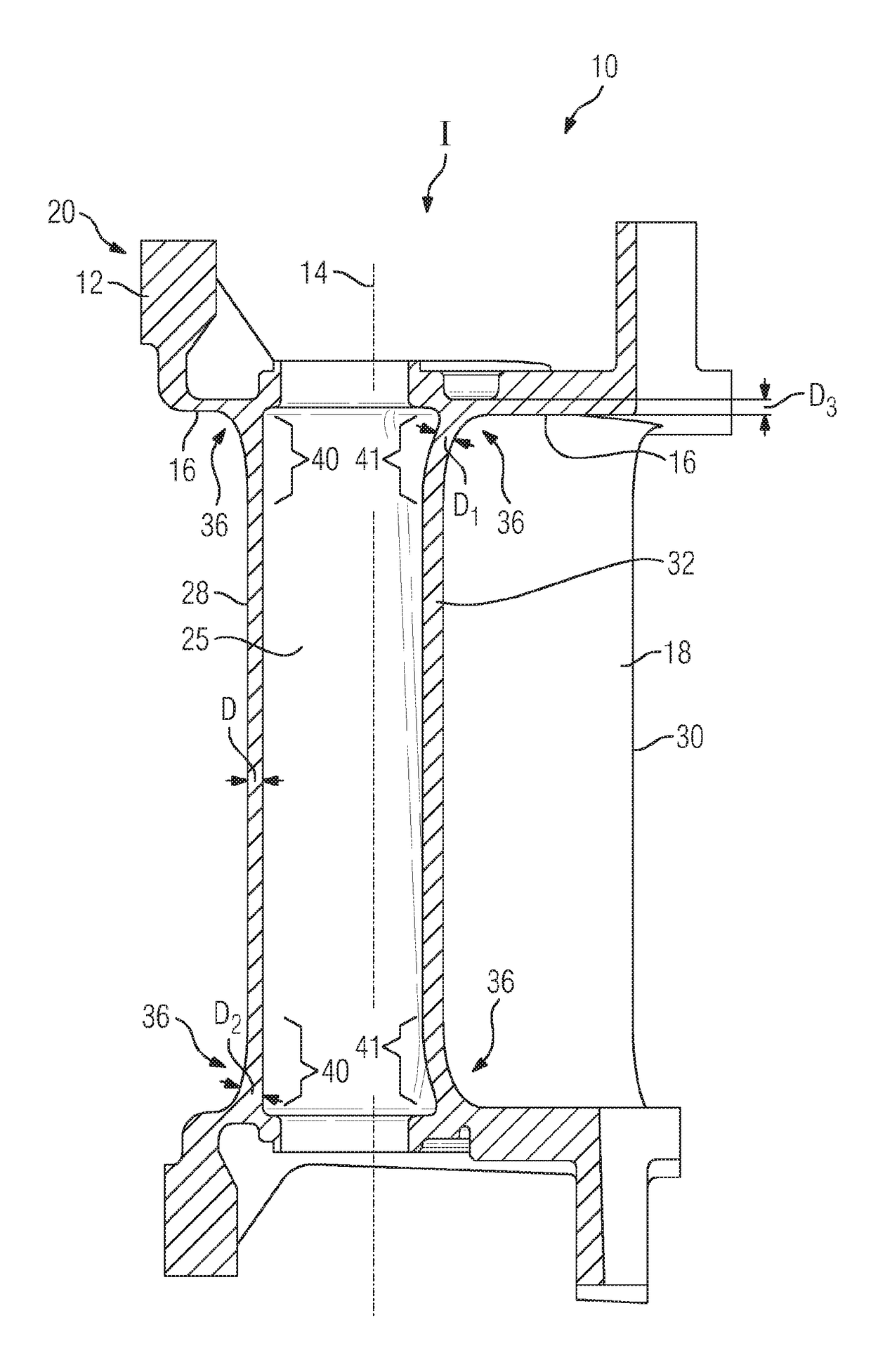
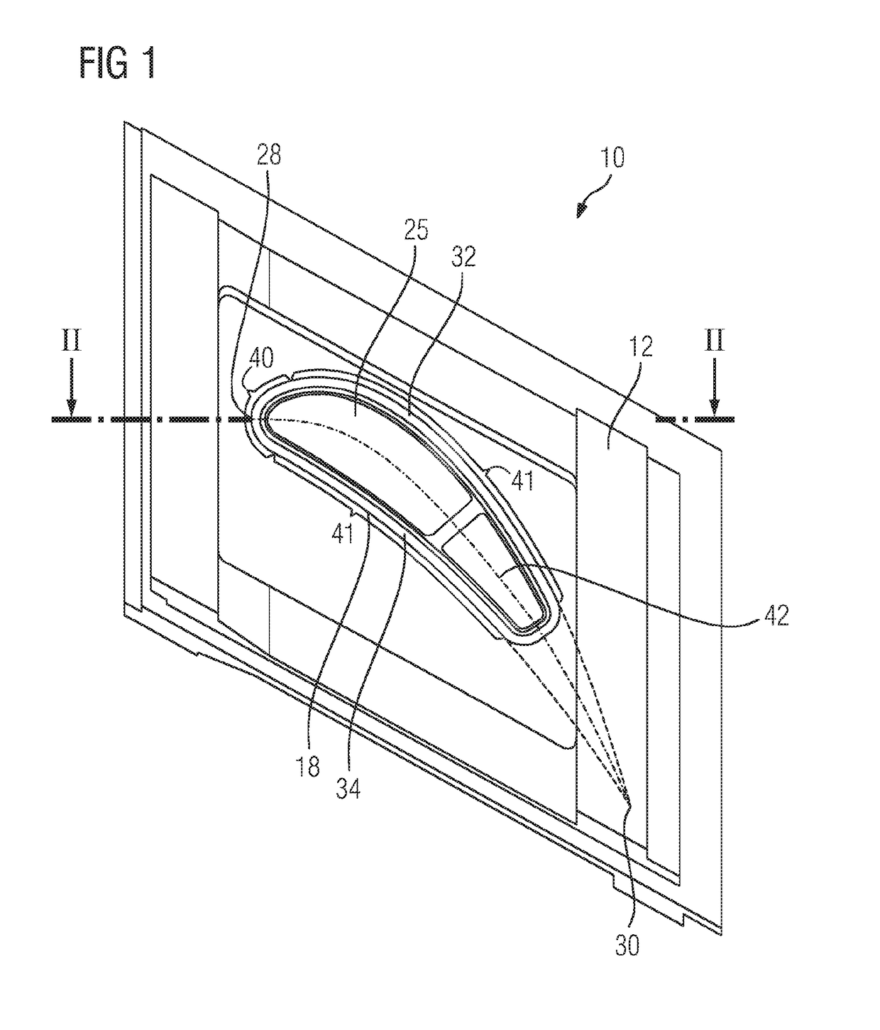
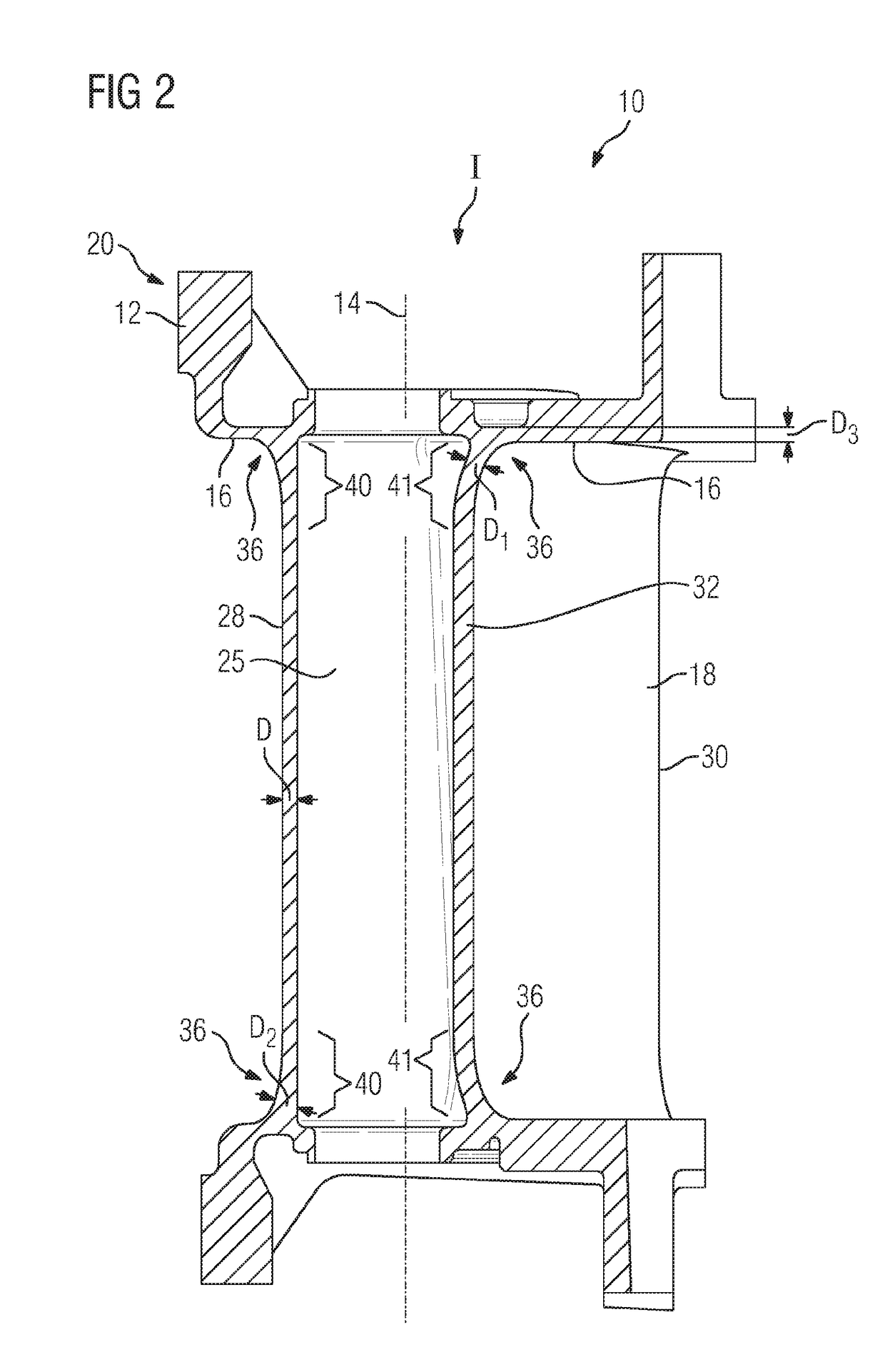
[0018]FIG. 1 shows a perspective view of a turbine blade 10. The perspective has been selected such that the plan view of a fastening region 12 of the turbine blade 10 configured as a guide vane is illustrated. FIG. 2 shows the longitudinal section through the turbine blade 10 on the section line II-II in FIG. 1. The turbine blade 10 has, in succession along a radial axis 14, the fastening region 12, a blade platform 16 adjoining the latter, and a blade airfoil 18. Formed in the fastening region 12 is a blade root 20 which serves for fastening the turbine blade 10 to a turbine guide vane support (not illustrated).

[0019]The invention is illustrated for example by way of a turbine blade configured as a guide vane with two platforms. Nevertheless, other configurations are possible, and in particular, the turbine blade can also be configured as a rotor blade of a turbine. At least the main body of the turbine blade is produced by a casting process and comprises at least the blade airfoi...


PUM


Abstract

A cast turbine blade having a platform and hollow blade airfoil arranged thereon, wherein the blade airfoil has a pressure-side blade wall and a suction-side blade wall that extend, along a centrally arranged curved profile centerline, from a common leading edge to a common trailing edge, and having a transition, with an outer contour profile, between the blade airfoil and the platform. The blade walls each have a locally determined blade wall thickness, wherein the turbine blade has, internally, a contour profile that partially matches the outer contour profile of the transition such that the region of the transition has an essentially constant blade wall thickness. In the transition, the contour profile at a surface section of the blade airfoil facing the leading edge is such that the blade wall thickness is increased there in comparison to the blade wall thickness of the transition away from the leading edge.

Description

CROSS REFERENCE TO RELATED APPLICATIONS[0001]This application is the US National Stage of International Application No. PCT / EP2016 / 064274 filed Jun. 21, 2016, and claims the benefit thereof. The International Application claims the benefit of European Application No. EP15175301 filed Jul. 3, 2015. All of the applications are incorporated by reference herein in their entirety.FIELD OF INVENTION[0002]The invention relates to a turbine blade.BACKGROUND OF INVENTION[0003]Hollow turbine blades, in particular gas turbine blades, have, in the region of a transition from the blade airfoil to the platform, a curvature, necessary in terms of loading and casting, on an outer surface, wherein accumulations of material arise locally in this fillet-like transition on account of a rectilinear inner design of the cooling ducts provided in the interior, said accumulations of material being harder to cool by a cooling medium that is able to flow there. Such turbine blades are known for example from U...

Claims


Application Information

Patent Timeline
Patent Type & Authority Applications(United States)
IPC IPC(8): F01D5/14F01D9/04
CPCF01D5/147F01D9/041F05D2230/21F05D2240/301F05D2240/80F05D2240/12F05D2220/32F01D5/14
Inventor BUCHHOLZ, BJORNGOSSILIN, RALPHKOCH, DANIELASCHULER, MARCO
Owner SIEMENS ENERGY GLOBAL GMBH & CO KG
Why Eureka
Try Eureka