Light source module

a technology of light source module and light source, applied in the direction of instruments, lighting and heating apparatus, semiconductor devices of light source, etc., can solve the problems of low space utility factor, short usable life span, heavy application product, etc., to prevent production difficulties, reduce mold size, good homogeneity

Inactive Publication Date: 2016-11-29
CAL COMP ELECTRONICS +1
View PDF5 Cites 0 Cited by
  • Summary
  • Abstract
  • Description
  • Claims
  • Application Information

AI Technical Summary

Benefits of technology

[0008]The disclosure provides a light source module having advantages of good homogeneity and simplified production.
[0010]Based on the above, the light source module of the embodiments of the disclosure may further control the proportion of the light beam reflected to the light emitting surface by the structural design of the first reflective structure and the second reflective structures, to adjust the homogeneity of the light. In addition, due to the different inclined surfaces of the plurality of second reflective structures, the light source module may achieve good homogeneity, and during optical design prevents difficulty of production caused if the design of the bottom of the base is curved. Also, the size of the mold may be decreased by the symmetrical structure design of the light source module, and a light source module of large dimension may be obtained by fabricating the light source modules in assembly, further decreasing the cost and difficulty of production.

Problems solved by technology

When using fluorescent lamps or CCFLs as an illumination light source, there are disadvantages such as it making the applicable product heavy, the usable life span short and the space utility factor low due to the usable life span and the size dimensions of the light source itself.
However, a majority of the reflective lamp covers of current light boxes in operation have a tablet design and is disadvantageous for performing optical designs to enhance the homogeneity of the emitted light.
And if performing surface design, it may also cause an increase in the difficulty of assembly, and be unfavorable for production.
Therefore, how to account for the homogeneity of the emitted light and the difficulty of production is an important issue for those skilled in the art in the technical field.
Also, the size of the mold may be decreased by the symmetrical structure design of the light source module, and a light source module of large dimension may be obtained by fabricating the light source modules in assembly, further decreasing the cost and difficulty of production.

Method used


Image

  • Light source module
  • Light source module
  • Light source module

Examples


Embodiment Construction

[0018]Reference will now be made in detail to the present preferred embodiments of the disclosure, examples of which are illustrated in the accompanying drawings. Wherever possible, the same reference numbers are used in the drawings and the description to refer to the same or like parts.

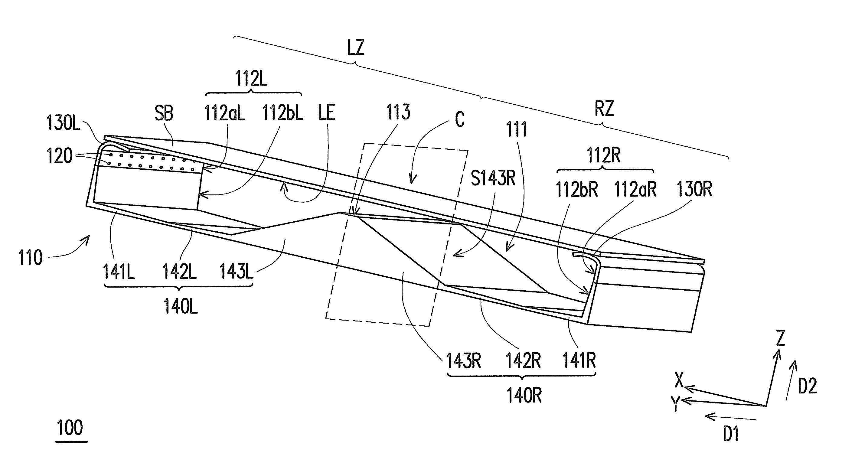
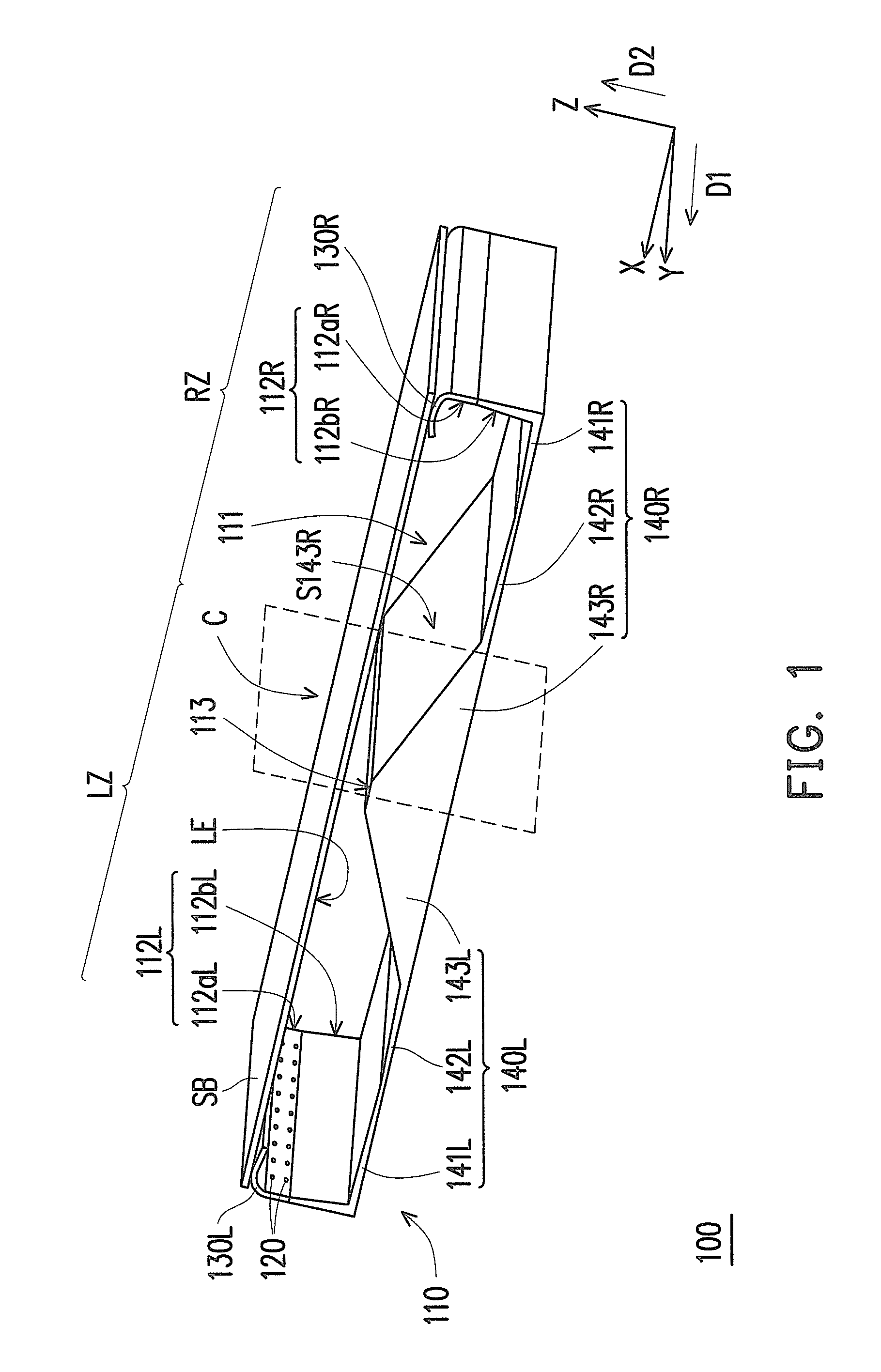
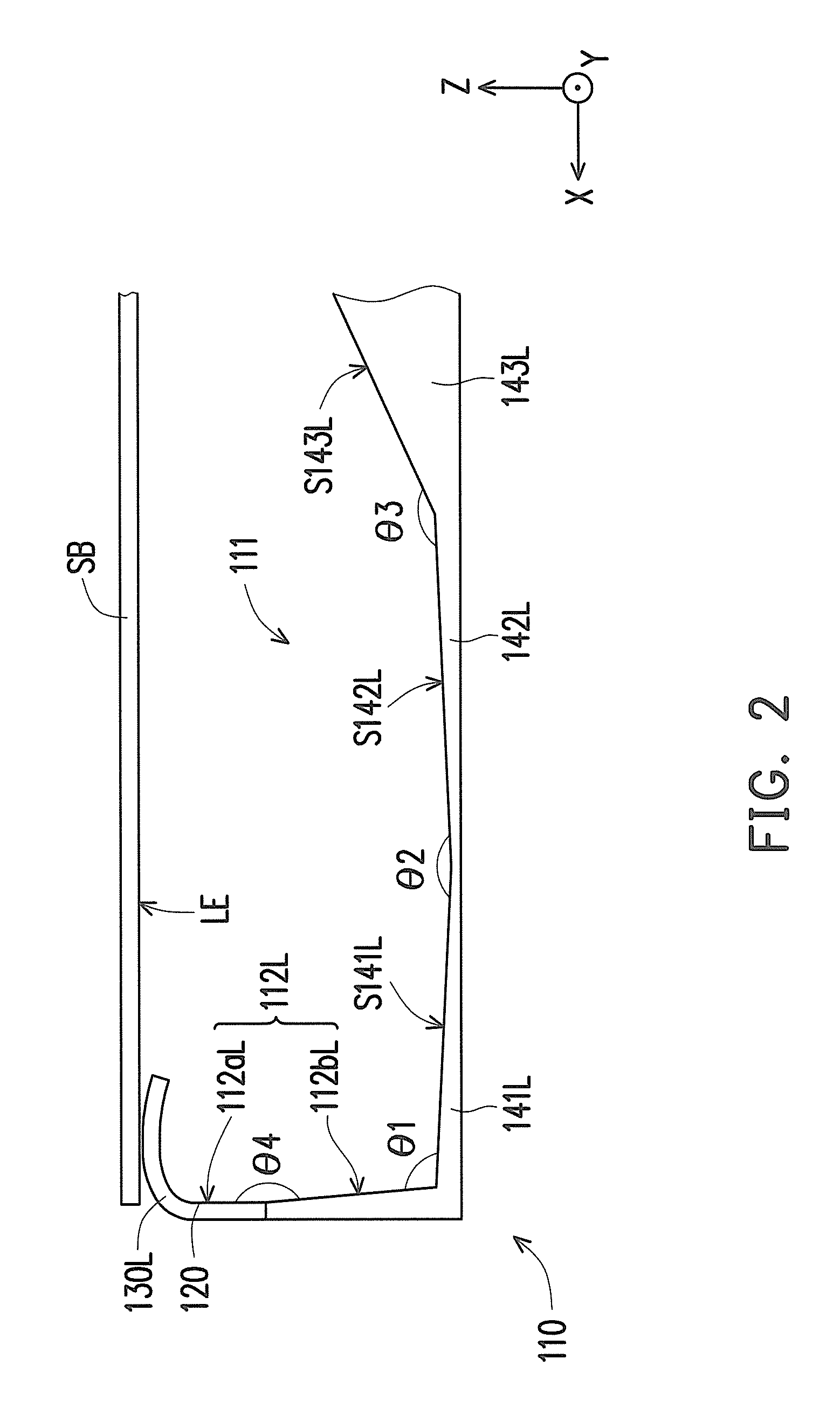
[0019]FIG. 1 is an architectural schematic diagram illustrating a light source module according to an embodiment of the disclosure. FIG. 2 is a structural schematic diagram illustrating a structure of a first reflective structure and a second reflective structure of FIG. 1. Referring to FIG. 1 and FIG. 2, a light source module 100 of the present embodiment is adapted for a signboard SB, where the signboard SB has a light emitting surface LE. The light source module 100 includes a base 110, at least one light source 120, at least one first reflective structure 130L and at least three second reflective structures 141L, 142L, 143L. For example, in the present embodiment, the light source 120 is an LED,...


PUM


Abstract

A light source module adapted for a signboard having a light emitting surface is provided. The light source module includes a base, at least one light source, at least one first reflective structure, and at least three second reflective structures. The base has a bottom and at least one side surface. The side surface is adjacent to the bottom and disposed between the bottom and the light emitting surface. The first reflective structure is adjacent to the side surface and far away from the bottom. The second reflective structures are disposed on the bottom. Part of the light beams provided by the light source ejects from the light emitting surface after reflected by one of the second reflective structures. Another part of the light beams ejects from the light emitting surface after reflected by the first reflective structure and one of the second reflective structures sequentially.

Description

CROSS-REFERENCE TO RELATED APPLICATION[0001]This application claims the priority benefit of Taiwan application serial no. 103143497, filed on Dec. 12, 2014. The entirety of the above-mentioned patent application is hereby incorporated by reference herein and made a part of this specification.BACKGROUND[0002]1. Technical Field[0003]The disclosure relates to a light source module, and relates particularly to a light source module having a plurality of reflective structures.[0004]2. Description of Related Art[0005]In conventional techniques, often times fluorescent lamps, cold cathode fluorescent lamps (CCFL) and light emitting diodes (LED) are used as a light source for lighting fixtures and advertisement light boxes. When using fluorescent lamps or CCFLs as an illumination light source, there are disadvantages such as it making the applicable product heavy, the usable life span short and the space utility factor low due to the usable life span and the size dimensions of the light sou...

Claims


Application Information

Patent Timeline
Patent Type & Authority Patents(United States)
IPC IPC(8): F21V1/00F21V7/04F21V7/00F21Y101/00
CPCF21V7/04F21V7/0008F21V7/0033F21Y2101/00G09F13/04G02B6/0096G09F13/14G09F2013/145F21Y2103/10F21Y2115/10
Inventor HUANG, YEN-HSIANGLIN, CHIH-FENGWANG, CHUN-MIN
Owner CAL COMP ELECTRONICS
Why Eureka
Try Eureka