
Method and apparatus for measuring drilling fluid properties

a technology of drilling fluid and measuring method, which is applied in the direction of direct flow property measurement, instruments, and borehole/well accessories, etc., can solve the problems of prone to errors that may prove costly in the drilling process, variations in the flow rate out of the funnel, and limited range of application of the devi

Active Publication Date: 2016-12-06
NAT OILWELL VARCO LP
View PDF30 Cites 6 Cited by
  • Summary
  • Abstract
  • Description
  • Claims
  • Application Information

AI Technical Summary

Problems solved by technology

These manual measurements are prone to errors that may prove costly in a drilling process.
Also, particles in the drilling fluid may segregate inside the funnel while the bottom of the funnel is plugged, which may lead to variations in flow rate out of the funnel that would not be accounted for by merely measuring time and the amount of fluid released into the container.
The range of application of the device is limited to those fluids that continue to flow freely as the level inside the funnel drops to very low values.
Other fluids not having this property may result in clogging of the funnel by surface tension forces.
However, this constant rotational speed has to be achieved by hand, which can be very difficult.
Particle settling can introduce errors to the measured shear torque.

Method used


Image

  • Method and apparatus for measuring drilling fluid properties
  • Method and apparatus for measuring drilling fluid properties
  • Method and apparatus for measuring drilling fluid properties

Examples


Embodiment Construction

[0024]Various illustrative embodiments of the present subject matter are described below. In the interest of clarity, not all features of an actual implementation are described in this specification. It will of course be appreciated that in the development of any such actual embodiment, numerous implementation-specific decisions must be made to achieve the developers' specific goals, such as compliance with system-related and business-related constraints, which will vary from one implementation to another. Moreover, it will be appreciated that such a development effort might be complex and time-consuming, but would nevertheless be a routine undertaking for those of ordinary skill in the art having the benefit of this disclosure.

[0025]The present subject matter will now be described with reference to the attached figures. Various systems, structures and devices are schematically depicted in the drawings for purposes of explanation only and so as to not obscure the present disclosure ...


PUM

PropertyMeasurementUnit
temperatureaaaaaaaaaa
fluid propertiesaaaaaaaaaa
viscosityaaaaaaaaaa

Abstract

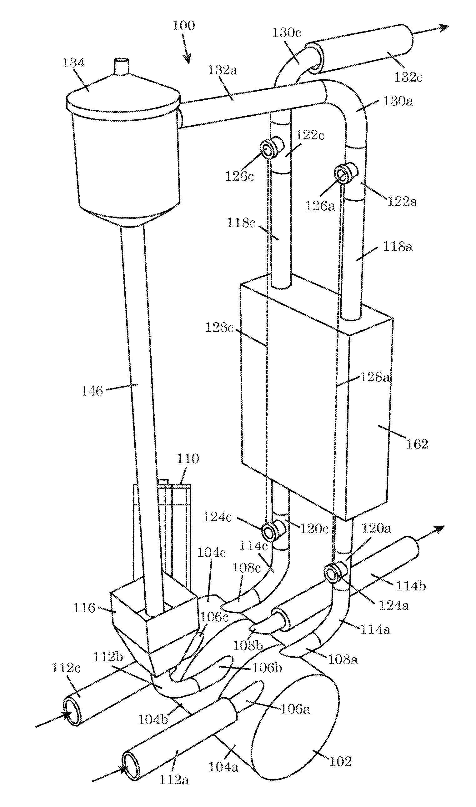
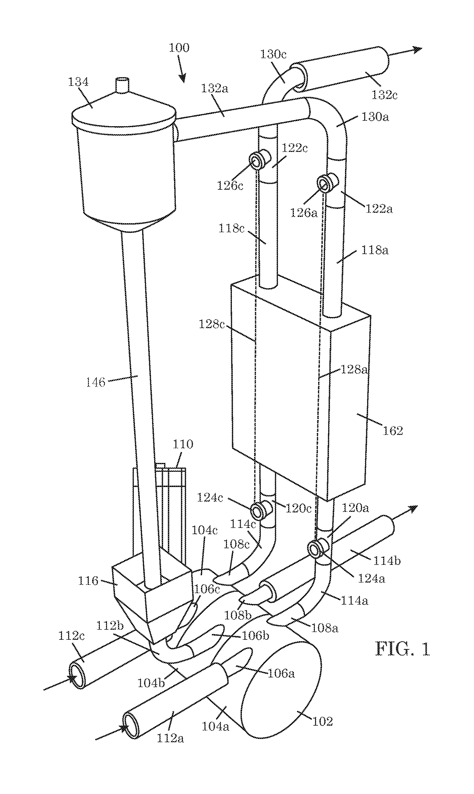
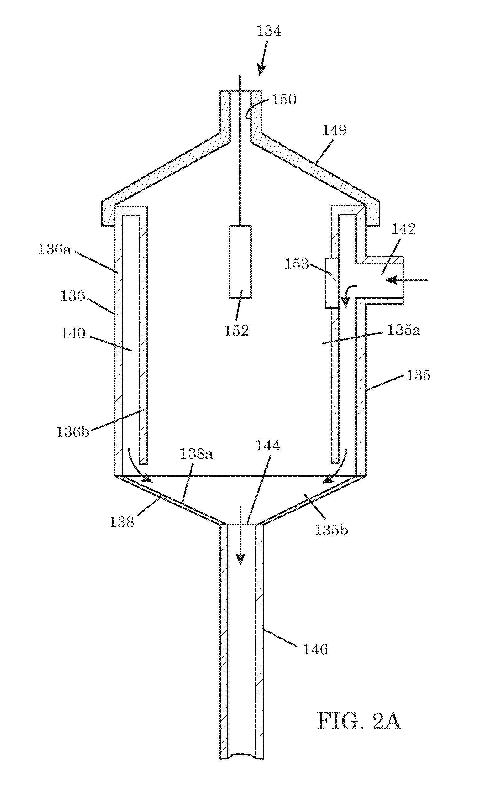
As system for measuring drilling fluid properties includes a capillary rheometer that is adapted to measure viscosity parameters of drilling fluid. The capillary rheometer includes a feed chamber, the feed chamber having a cavity, at least a first drain port for draining fluid out of the cavity, a double wall defining an annulus that opens to the cavity, and a feed port in an outer portion of the double wall that is in fluid communication with the annulus. The capillary rheometer also includes at least a first capillary tube coupled to at least the first drain port. Additionally, the disclosed system further includes a pump that is adapted to pump fluid to the feed port.

Description

BACKGROUND[0001]1. Field of the Disclosure[0002]The present disclosure is generally directed to drilling fluids that are used during drilling operations for oil and gas wells, and in particular, to methods and apparatuses for analyzing the properties of such drilling fluids.[0003]2. Description of the Related Art[0004]Drilling fluid, or “mud,” is a multicomponent fluid specially formulated to perform various functions during drilling of an oil or gas well. Examples of such functions include cooling the drill bit, lubricating and sealing the wall of the well, providing hydrostatic pressure in the well annulus to prevent formation fluid influx, clearing away drilled solids from the drill bit, and returning drilled solids to the surface. Circulation of the drilling fluid through the well typically involves pumping the drilling fluid down the bore of a drill string in the well, whereby the drilling fluid jets through nozzles in a drill bit at the end of the drill string into the bottom ...

Claims


Application Information

Patent Timeline
Patent Type & Authority Patents(United States)
IPC IPC(8): G01N33/28G01N11/08G01N11/00E21B49/08
CPCG01N33/2823G01N11/08E21B2049/085G01N2011/0026E21B49/0875
Inventor LARSON, THOMAS ROBERT
Owner NAT OILWELL VARCO LP
Learn More