Floating hybrid composite wind turbine platform and tower system

a wind turbine platform and hybrid technology, applied in the field of floating wind turbine platforms, can solve the problems of unsatisfactory aesthetics, unsatisfactory wind turbines, and inability to achieve the optimal flow of air on land

Active Publication Date: 2016-12-13
UNIVERSITY OF MAINE
View PDF68 Cites 9 Cited by
  • Summary
  • Abstract
  • Description
  • Claims
  • Application Information

AI Technical Summary

Problems solved by technology

These large groups of wind turbines can generate undesirably high levels of noise and may be viewed as aesthetically unpleasing.
An optimum flow of air may not be available to these land-base wind turbines due to obstacles such as hills, woods, and buildings.
The foundations required to attach wind turbines to the seabed at these near-coast locations is relatively expensive, and can only be accomplished at relatively shallow depths, such as a depth of up to about 25 meters.
Fixed foundations for wind turbines in such deep water are not likely economically feasible.
This limitation has led to the development of floating platforms for wind turbines.

Method used


Image

  • Floating hybrid composite wind turbine platform and tower system
  • Floating hybrid composite wind turbine platform and tower system
  • Floating hybrid composite wind turbine platform and tower system

Examples


first embodiment

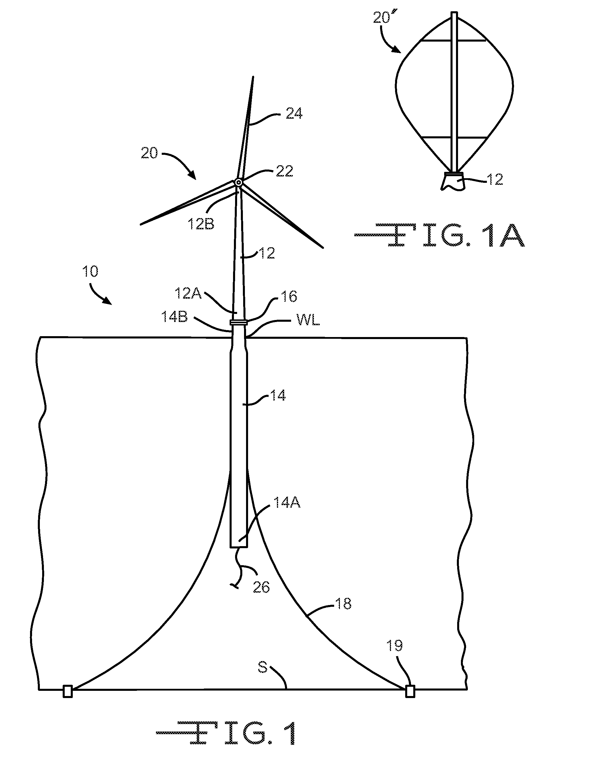
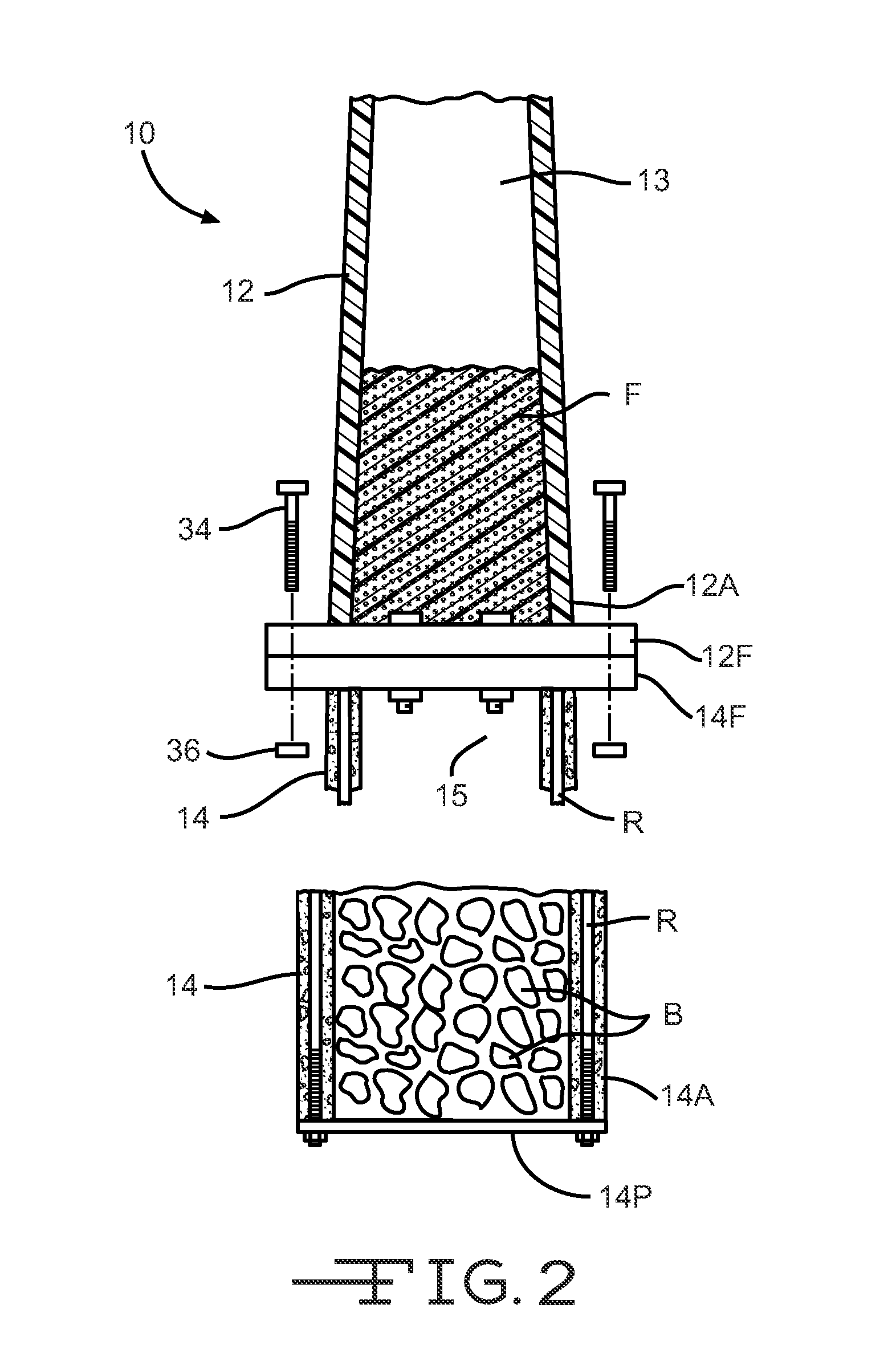
[0050]Referring to the drawings, particularly to FIG. 1, a floating composite wind turbine platform 10 is shown anchored to the seabed S. The illustrated floating wind turbine platform 10 is a ballast stabilized, spar buoy type platform and includes a tower 12 attached to a hull 14 at a connection joint 16. Mooring lines 18 are attached to the hull 14 and further anchored to the seabed S by anchors 19. A wind turbine 20 is mounted to the tower 12.

[0051]A spar buoy type platform maintains its stability afloat by keeping its center of gravity below its center of buoyancy. This relationship of the center of gravity being below the center of buoyancy is often achieved by filling a heavy long tube or hull with ballast comprising water and dense material such as rocks.

[0052]In the embodiments illustrated herein, the wind turbine 20 is a horizontal-axis wind turbine. Alternatively, the wind turbine may be a vertical-axis wind turbine, such as shown at 20′ in FIG. 1A. The size of the turbin...

second embodiment

[0067]Referring to FIG. 19, a floating composite wind turbine platform is shown at 10′. The illustrated floating wind turbine platform 10′ is substantially similar to the floating composite wind turbine platform is shown at 10, but the tower 12 and the hull 14 are formed as a one-piece tower / hull member 11. In this embodiment, the connection joint 16 is not required. The one-piece tower / hull member 11 may be formed from FRP composite in the same manner as the tower 12, described in detail above. Alternatively, the one-piece tower / hull member 11 may be formed from may be formed from reinforced concrete in the same manner as the hull 14, described in detail above.

[0068]The interior of the tower / hull member 11 defines an elongated cavity 17 within the tower / hull member 11. In the illustrated embodiment, a wall 38 extends transversely within the cavity 17 and divides the cavity 17 into a tower cavity portion 13′ and a hull cavity portion 15′. At least a portion of the tower cavity porti...

third embodiment

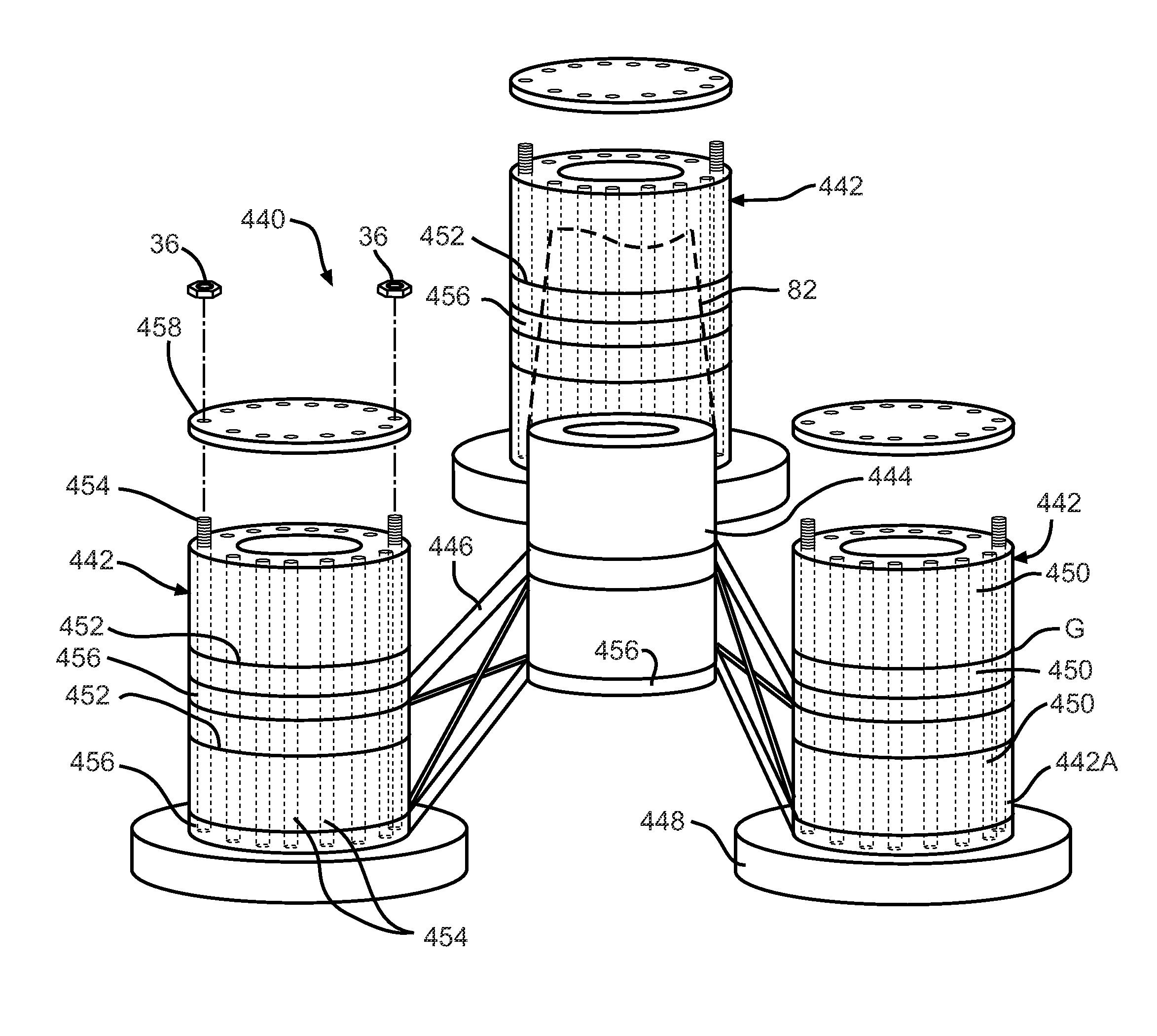
[0097]Referring now to FIG. 11, a floating composite wind turbine platform 60 is shown anchored to the seabed S. The illustrated floating wind turbine platform 60 is similar to the mooring line stabilized, tension leg type platform 40 illustrated in FIG. 8 and includes a tower 62 attached to the hull platform 44 at a connection joint 66. Mooring lines 48 are attached to the hull platform 44 and further anchored via anchors 19 to the seabed S. The wind turbine 20 is mounted to the tower 62. Cable stays 64 are attached to the hull platform 44 and further attached to the tower 62.

[0098]In the illustrated embodiment, the tower 62 is formed as a tube and is fabricated from fiber reinforced polymer (FRP) composite material. Non-limiting examples of suitable FRP composite material include glass and carbon FRP. Alternatively, the tower 62 may be formed from concrete or from steel, as described above.

[0099]Because the cable stays 64 reduce bending stress in the tower 62, the tower 62 can be ...


PUM

PropertyMeasurementUnit
depthaaaaaaaaaa
depthsaaaaaaaaaa
depthsaaaaaaaaaa

Abstract

A wind turbine platform is configured for floating in a body of water and includes a hull defining a hull cavity therein. The hull is formed from reinforced concrete. A tower is configured to mount a wind turbine and is also connected to the hull. An anchor member is connected to the hull and to the seabed.

Description

BACKGROUND[0001]Various embodiments of a wind turbine platform are described herein. In particular, the embodiments described herein relate to an improved floating wind turbine platform for use in large bodies of water.[0002]Wind turbines for converting wind energy to electrical power are known and provide an alternative energy source for power companies. On land, large groups of wind turbines, often numbering in the hundreds of wind turbines, may be placed together in one geographic area. These large groups of wind turbines can generate undesirably high levels of noise and may be viewed as aesthetically unpleasing. An optimum flow of air may not be available to these land-base wind turbines due to obstacles such as hills, woods, and buildings.[0003]Groups of wind turbines may also be located offshore, but near the coast at locations where water depths allow the wind turbines to be fixedly attached to a foundation on the seabed. Over the ocean, the flow of air to the wind turbines i...

Claims


Application Information

Patent Timeline
Patent Type & Authority Patents(United States)
IPC IPC(8): B63B35/44B63B5/14B63B5/24B63B1/10B63B3/04F03D1/00
CPCF03D13/20B63B5/14B63B5/24B63B35/44F05B2240/95Y02E10/727Y02E10/728B63B1/107B63B3/04B63B2035/442B63B2035/446B63B2231/04B63B2231/50B63B2231/52B63B2231/66B63B2231/68F03D1/006F05B2240/912F05B2240/93B63B1/048B63B2001/044F03D13/25F03D13/30Y02E10/72B63B21/50B63B2231/60
Inventor DAGHER, HABIB J.VISELLI, ANTHONY M.GOUPEE, ANDREW J.
Owner UNIVERSITY OF MAINE
Why Eureka
Try Eureka