Physical cable lead identifier for medical systems

Active Publication Date: 2016-12-20
GENERAL ELECTRIC CO
View PDF7 Cites 5 Cited by
  • Summary
  • Abstract
  • Description
  • Claims
  • Application Information

AI Technical Summary

Benefits of technology

[0007]According to one exemplary aspect of the invention, a catheter identification system includes an input module, such as a pin box or other suitable connector for the catheter that includes a number of ports capable of receiving a catheter therein. The input module/pin box is in turn connected to an electrophysiological (EP) or other recording or mapping device or system, such that signals received from or sent to the catheters can be monitored by the device. In order to correlate the catheters engaged with the various ports on the pin box with the displays presented by the device or system, the pin box includes a light source, such as a light emitting diode (LED), disposed on the pin box adjacent each port. When a catheter is connected to a port on the pin box, a central processing unit (CPU) for the display on the device can send a signal to a controller located within the input module/pin box for the light source to operate the light source to correspond to the color of the signal from the catheter connected at that port on the display. Thus, when a signal on the display appears erratic or incorrect for any of a number of reasons, the clinician can simply look at the pin box to locate the port at which the color of the light source corresponds to the color of the signal on the display. In this manner, the pin box can efficiently direct the clinician to the catheter at issue, eliminating the need to review the connections for multiple catheters to locate any problems.
[0008]According to another aspect of an exemplary embodiment of the inventi

Problems solved by technology

This modulation of the light source can also take place when the signals received

Method used


Image

  • Physical cable lead identifier for medical systems
  • Physical cable lead identifier for medical systems
  • Physical cable lead identifier for medical systems

Examples


Example

DETAILED DESCRIPTION OF THE DRAWINGS

[0022]In the following detailed description, reference is made to the accompanying drawings that form a part hereof, and in which is shown by way of illustration specific embodiments, which may be practiced. These embodiments are described in sufficient detail to enable those skilled in the art to practice the embodiments, and it is to be understood that other embodiments may be utilized and that logical, mechanical, electrical and other changes may be made without departing from the scope of the embodiments. The following detailed description is, therefore, not to be taken in a limiting sense.

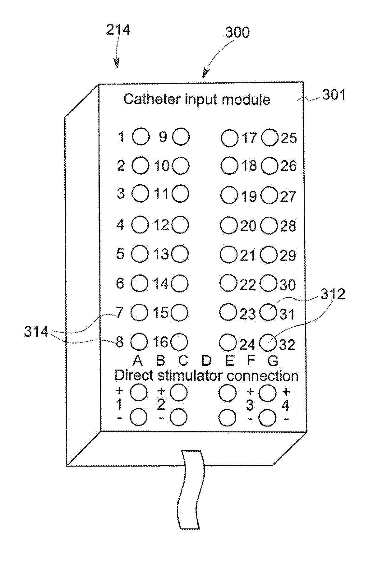
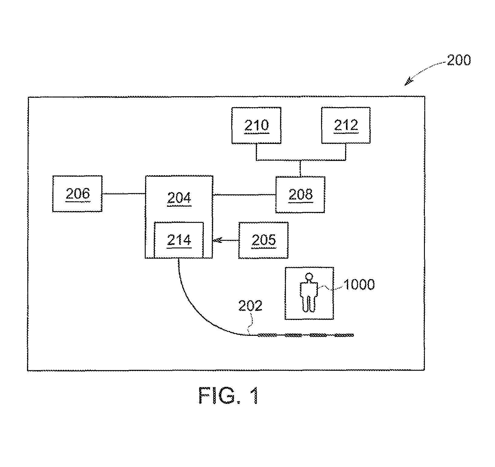
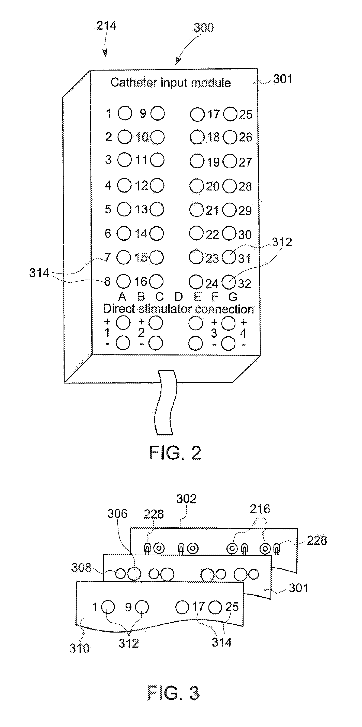
[0023]FIG. 1 illustrates one exemplary embodiment of an electrophysiology (EP) mapping or an EP recorder system 200, such as those used in intracardiac electrocardiography (ECG) studies within the body of a patient 1000. These systems 200 apply / receive an electrical signal (e.g., electrical current) via one or more catheters 202 to various locations of the b...


PUM


Abstract

In the present invention, an electrophysiology (EP) mapping or recording device for obtaining and recording information on a patient connected to the EP system includes a central processing unit (CPU), a display connected to the CPU, a catheter connected to the CPU by a catheter input module and configured to supply a physiological signal to the CPU via the input module and a catheter identification system connected between the input module catheter and the CPU. The identification system includes a driver circuit that communicates with the CPU to determine a color of a visual representation of the signal from the catheter on the display and a light source connected to the driver circuit. The light source is operated by the driver circuit to emit light corresponding to the color of the representation on the display to identify the catheter in conjunction with the representation on the display.

Description

BACKGROUND OF INVENTION[0001]The invention relates generally to identification systems for cable leads or catheters, and more particularly to identification systems that enable the cable leads or catheters to be specifically identified by and correlated to the visual representation of the signal from the catheter on the display of the electrophysiological (EP) or other recording or mapping device or system to which the catheters are connected during studies or monitoring of patients.[0002]Catheters are used in an increasing number of medical procedures to evaluate various conditions of the patient with which the catheter is utilized. While many different numbers and / or configurations of catheters can be utilized for a particular procedure, for each procedure all of the catheters in use must be properly connected to the recording or mapping device such that the signals received from or sent to a particular catheter are correctly identified and displayed by the recording or mapping de...

Claims


Application Information

Patent Timeline
IPC IPC(8): A61N1/375A61B5/042G08B5/36A61B5/00
CPCA61B90/92A61B5/042A61B5/742G08B5/36A61B5/6852A61B2562/08A61B5/287A61B5/304
Inventor SCHMIT, RODGER F.WARNER, ADRIAN F.SCHNEIDEWEND, DANIEL R.STIEMKE, TIMOTHY P.
Owner GENERAL ELECTRIC CO
Why Eureka
Try Eureka