

Sound Absorbing Element and Method for Producing a Sound Absorbing Element
- Summary
- Abstract
- Description
- Claims
- Application Information
AI Technical Summary
Benefits of technology
Problems solved by technology
Method used
Image

Examples
Embodiment Construction
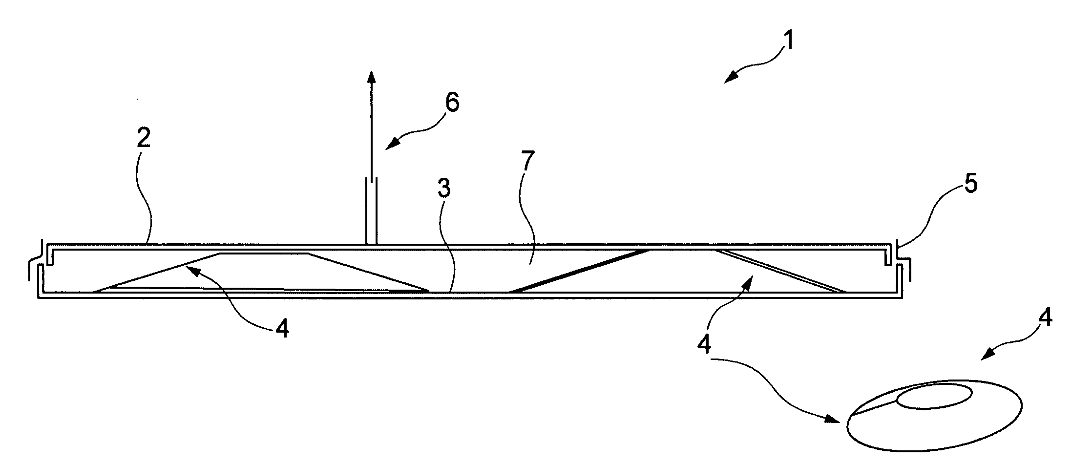
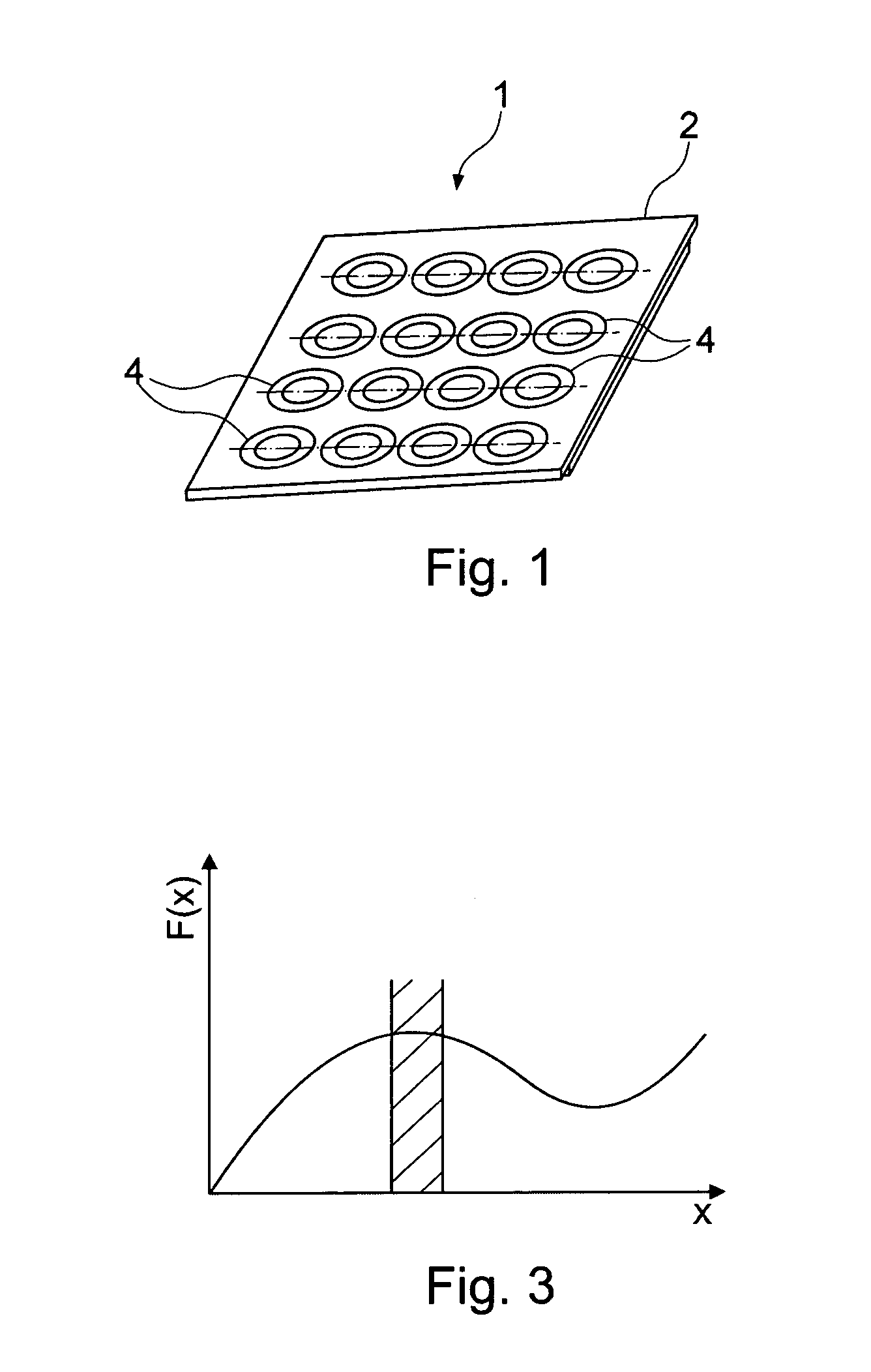
[0023]FIG. 1 shows a perspective view of a sound absorbing element 1 according to an exemplary embodiment of the invention, in which sound absorbing element 1 a first wall area 2 and a second wall area 3 are arranged so as to be spaced apart by a plurality of spring elements 4, which in the arrangement shown are saucer springs 4. For the sake of clarity the first wall area 2 is shown so as to be transparent, in order to better show the interior of the sound absorbing element 1 according to the exemplary embodiment of the invention. In this arrangement the saucer springs 4 are arranged in a regular rectangular grid relative to each other so that, as even as possible, a decoupling of the first wall area 2 from the second wall area 3 is achieved.
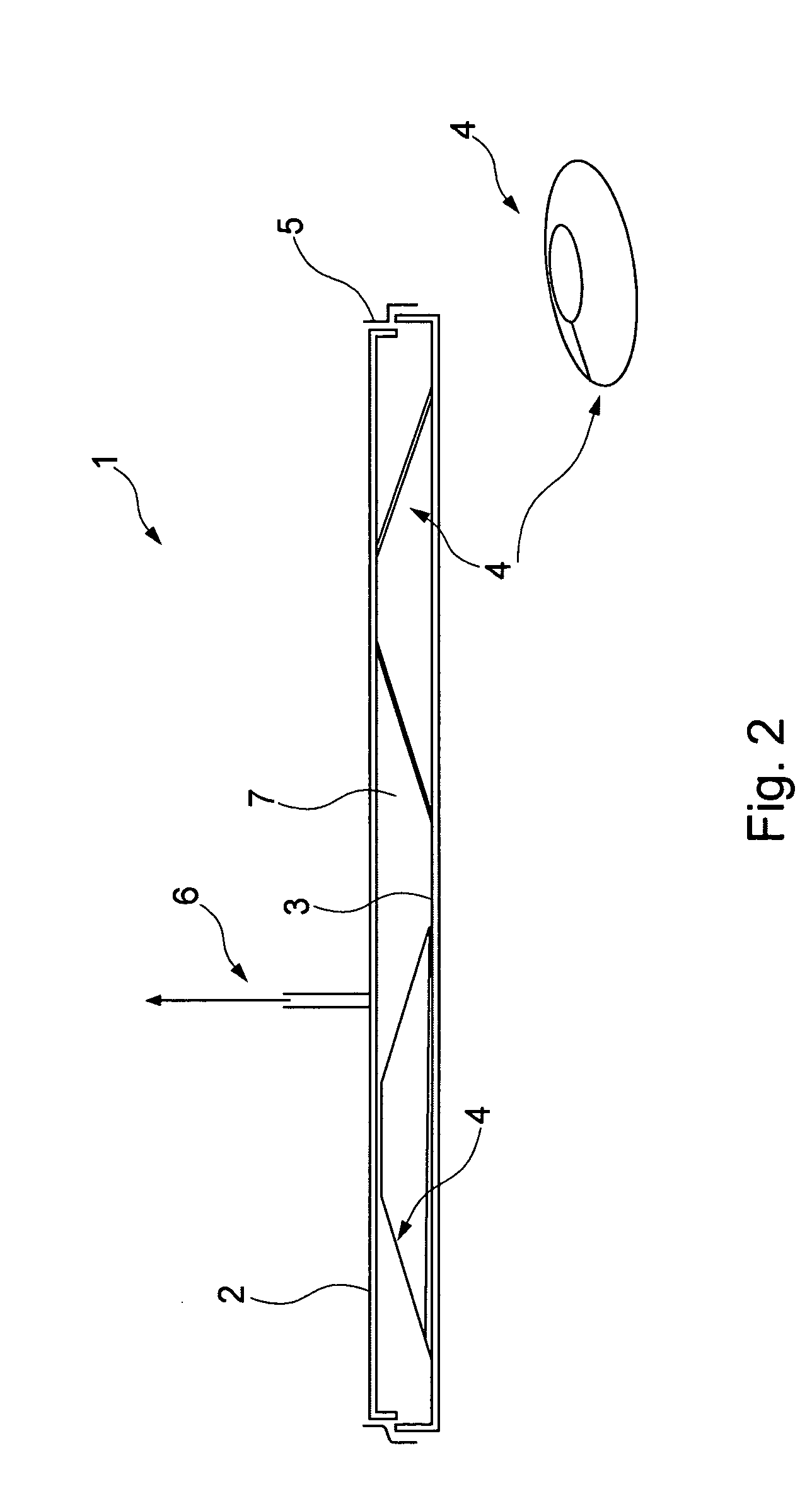
[0024]As can better be seen in FIG. 2 the first wall area 2 and the second wall area 3 are arranged spaced apart from each other by a clear space 7. In this clear space 7 in the embodiment shown two saucer springs 4 are arranged, which connect ...
PUM
| Property | Measurement | Unit |
|---|---|---|
| Fraction | aaaaa | aaaaa |
| Pressure | aaaaa | aaaaa |
Abstract
Description
Claims
Application Information