
Method and apparatus for transmitting high bandwidth signals with low bandwidth transponders

a transponder and high-bandwidth technology, applied in the field of system and method for spectrally efficient transmission of signals, can solve the problems of significant waste of wireless channel capacity, 15 mbps, and the inability to compress video in time, and achieve the effect of increasing latency

Active Publication Date: 2016-12-20
DIRECTV LLC
View PDF39 Cites 4 Cited by
  • Summary
  • Abstract
  • Description
  • Claims
  • Application Information

AI Technical Summary

Benefits of technology

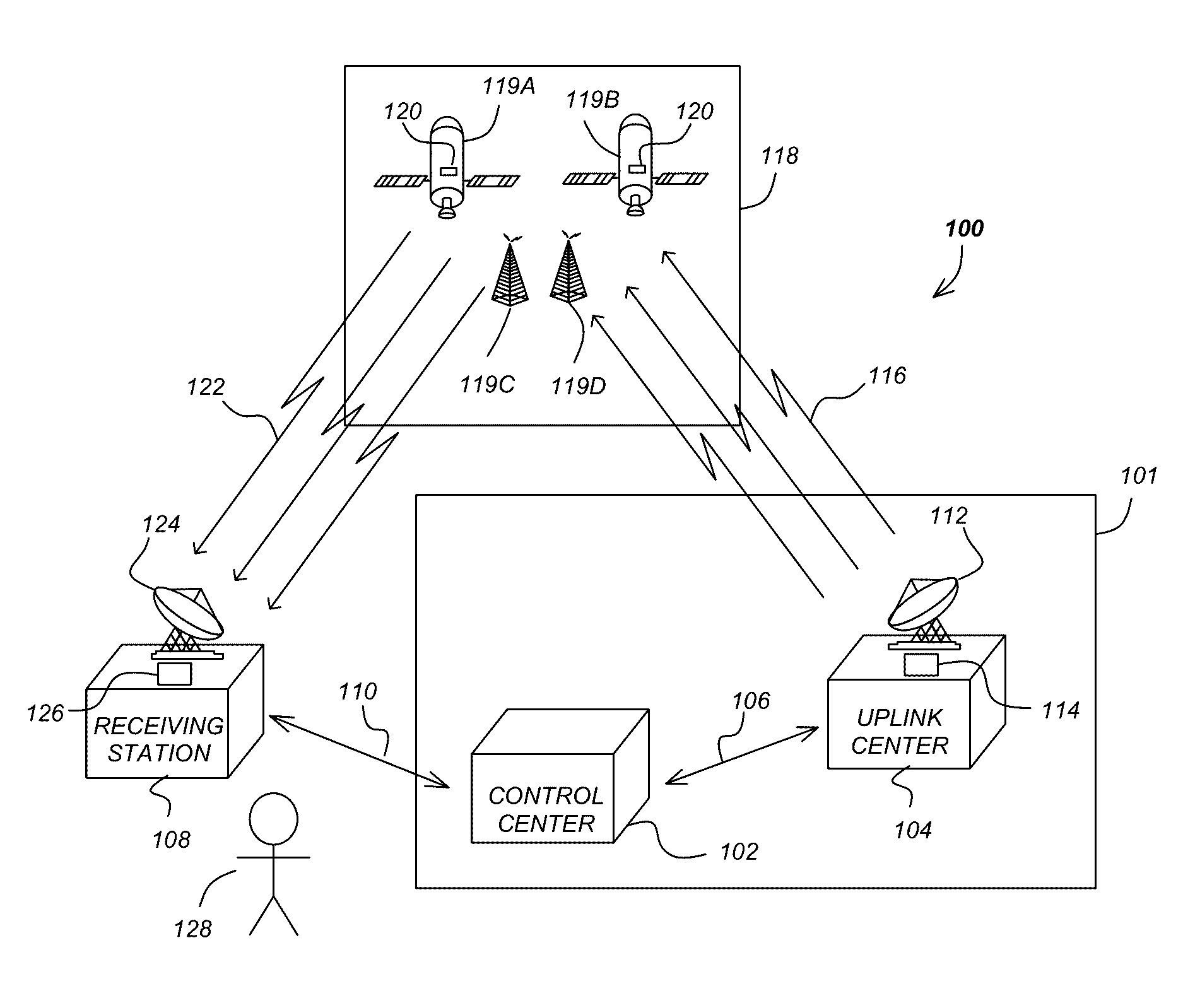
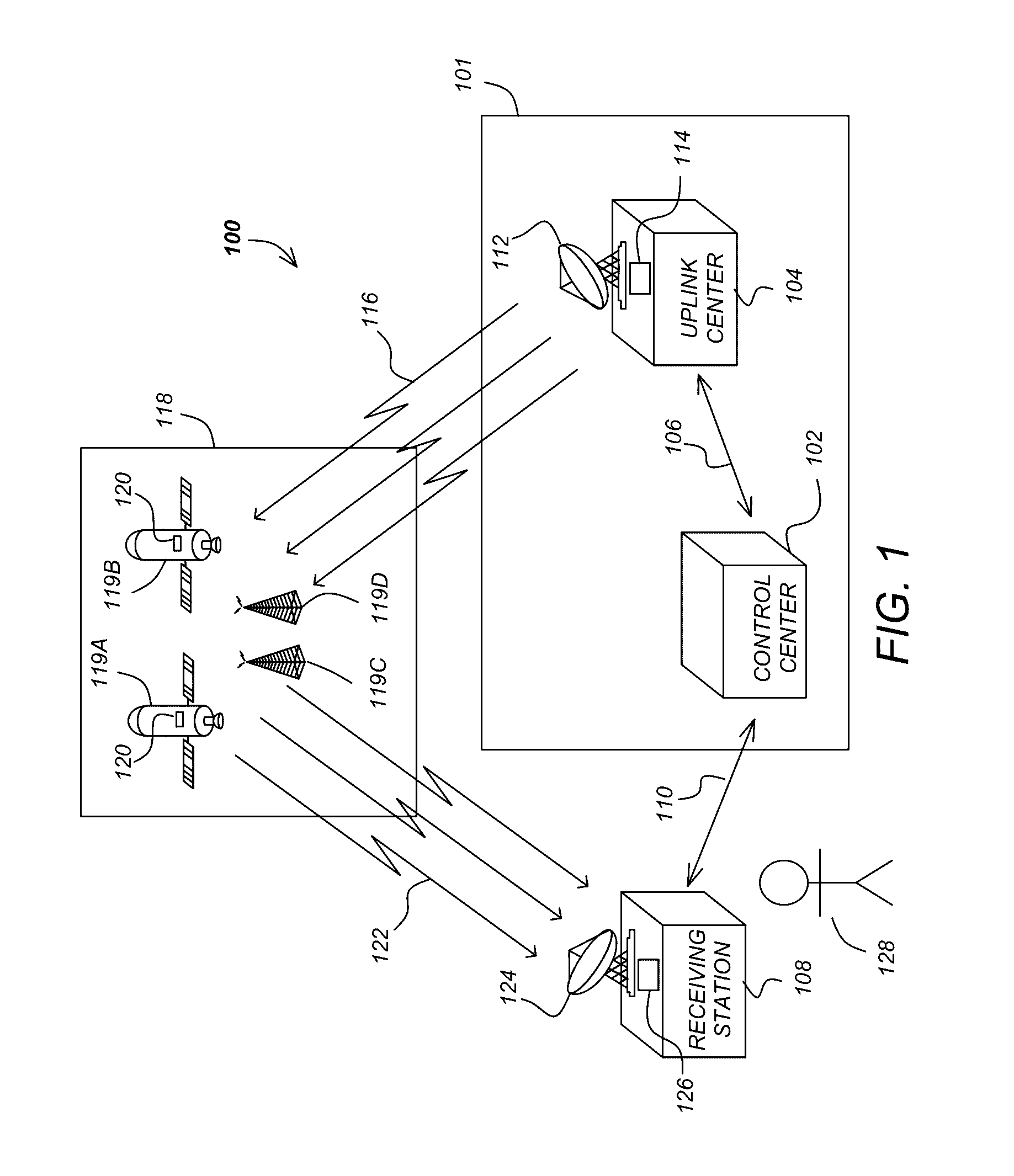
[0013]Hence, N broadcast sub-transmitters can be used to transmit K multiple video signals that have been statistically multiplexed together and uplinked as M data streams. The statistically multiplexed video signals constitute a “fat pipe” that is then split up and transmitted over multiple “bonded” transponders in a manner that allows reconstitution of the fat pipe at the receiver without loss of data and without increased latency.

Problems solved by technology

Transmission of video signals over fixed capacity transmission channels poses a number of technical challenges.
Raw, uncompressed video requires bandwidth that can exceed the available bandwidth on a satellite channel by orders of magnitude.
If the peak bit-rate of a compressed video signal exceeds its average bit-rate by a significant amount (usually the case with most types of content) there is a significant waste of the wireless channel capacity.
For example, if the average video bit-rate is 10 mbps and its peak bit-rate is 25 mbps, it would require a satellite channel with a capacity of at least 25 mbps, but on average, 15 mbps, of capacity will be wasted.
With the advent of high-bit rate content such as 4KTV, full resolution 3DTV and even 1080p60 content, existing satellite transponders will not have the capacity of transmitting several such streams, even if they are statistically multiplexed together.

Method used


Image

  • Method and apparatus for transmitting high bandwidth signals with low bandwidth transponders
  • Method and apparatus for transmitting high bandwidth signals with low bandwidth transponders
  • Method and apparatus for transmitting high bandwidth signals with low bandwidth transponders

Examples


Embodiment Construction

[0028]In the following description, reference is made to the accompanying drawings which form a part hereof, and in which is shown by way of illustration one or more specific embodiments. It is to be understood that other embodiments may be utilized and structural changes may be made without departing from the scope of the present disclosure.

Overview

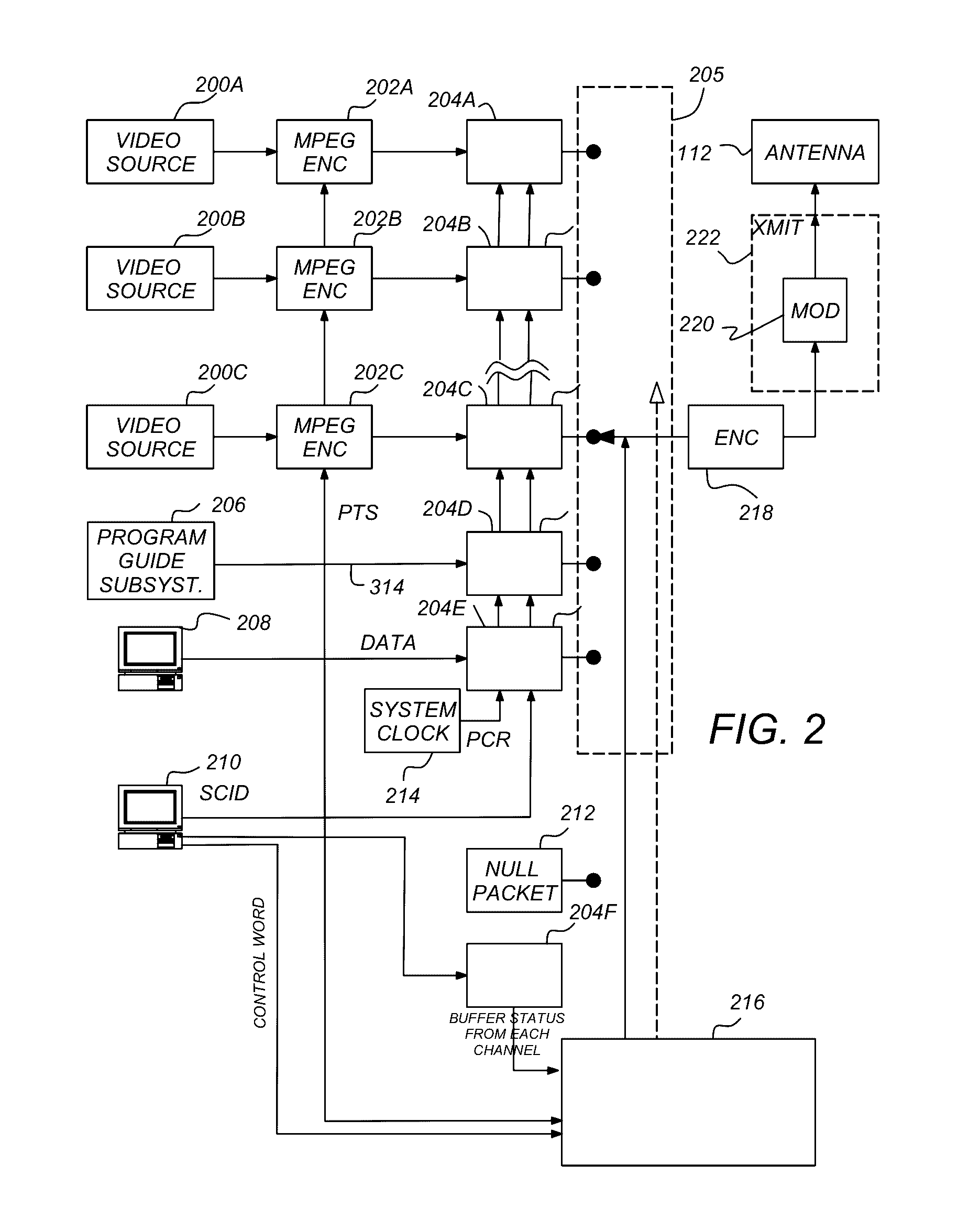
[0029]Transponder bandwidths are combined using a wide-band “virtual” transponder comprising a plurality of narrow-band physical transponders for transmitting a single data stream. A plurality of elementary streams are statistically multiplexed to create the single data stream. The single data stream is forward error correction encoded for channel impairment correction. The single encoded data stream is demultiplexed into a plurality of transponder streams, and each transponder stream is modulated and transmitted to the receivers. Upon receipt from the plurality of narrow-band physical transponders, the transponder streams are demodulate...


PUM


Abstract

A method and apparatus for transmitting a plurality of elementary data streams to a plurality of receivers is disclosed. In one embodiment, the method comprises the steps of generating M data streams comprising K multiplexed elementary data streams in a first entity, transmitting the M data streams to a second entity, generating N transmitter streams from the M data streams in the second entity; and transmitting each of the N transmitter streams to the plurality of receivers using an associated one of N broadcast sub-transmitters.

Description

CROSS-REFERENCE TO RELATED APPLICATIONS[0001]This application is a continuation-in-part (CIP) of U.S. patent application Ser. No. 13 / 484,756, entitled “COMBINING TRANSPONDER BANDWIDTHS FOR SOURCE AND FEC ENCODING EFFICIENCY,” by Ernest Chen, filed May 31, 2012, which is a continuation of U.S. application Ser. No. 11 / 193,856, entitled “COMBINING TRANSPONDER BANDWIDTHS FOR SOURCE AND FEC ENCODING EFFICIENCY,” by Ernest Chen, filed Jul. 29, 2005, now issued as U.S. Pat. No. 8,200,149, issued Jun. 12, 2012, all of which applications are hereby incorporated by reference herein.TECHNICAL FIELD[0002]The present disclosure relates to systems and methods for the spectrally efficient transmission of signals, and more particularly, for combining transponder bandwidths for source and forward error correction encoding efficiency.BACKGROUND FIELD[0003]Digital Direct Broadcast Systems (DBS) have become very successful. However, as such systems evolve, there is an increasing demand for additional b...

Claims


Application Information

Patent Timeline
Patent Type & Authority Patents(United States)
IPC IPC(8): H04W4/06
CPCH04W4/06H04N21/23655H04N21/2662H04N21/6193
Inventor PONTUAL, ROMULOBASSE, HANNOPEJHAN, SASSANSANTORU, JOSEPHCHEN, ERNEST C.
Owner DIRECTV LLC
Learn More