
Thin front channel photopolymer drop ejector

a technology of photopolymer drop and ejector, which is applied in the direction of printing and inking apparatus, can solve the problems of short matter of time before ink is dried out, and achieve the effects of reducing the drop volume of thermal ink jet drop ejector, prolonging the latency time of a given head design and ink combination, and improving the latency of ink/printhead combination

Inactive Publication Date: 2003-01-21
XEROX CORP
View PDF8 Cites 2 Cited by
  • Summary
  • Abstract
  • Description
  • Claims
  • Application Information

AI Technical Summary

Benefits of technology

It would be desirable to implement a ink jet printhead which allows usage of a greater variety of inks including viscous inks and to also improve the latency of the ink / printhead combination. This would be desirable so as to open up ink property latitudes so as to allow "no-compromise" inks and to reduce the drop volume of thermal ink jet drop ejectors. However, given the need for a heater element and the limited volume amount of ink in the channel, it is only a short matter of time before the ink is dried out in the channel. The amount of time before such drying problems become exhibited is referred to as latency. The longer the latency time for a given head design and ink combination the better. It also follows that improving latency for a given head design will also open up the range of inks which can then be employed by that printhead.
Therefore, as discussed above, there exists a need for a design arrangement which will solve the problem of improving latency in thermal ink jet heads and providing a greater latitude in, and variety of, inks. Thus, it would be desirable to solve this and other deficiencies and disadvantages with an improved ink jet printhead apparatus.

Problems solved by technology

However, given the need for a heater element and the limited volume amount of ink in the channel, it is only a short matter of time before the ink is dried out in the channel.

Method used


Image

  • Thin front channel photopolymer drop ejector
  • Thin front channel photopolymer drop ejector
  • Thin front channel photopolymer drop ejector

Examples


Embodiment Construction

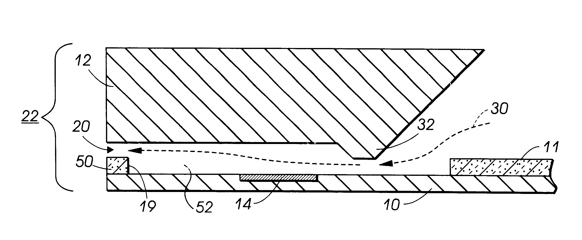
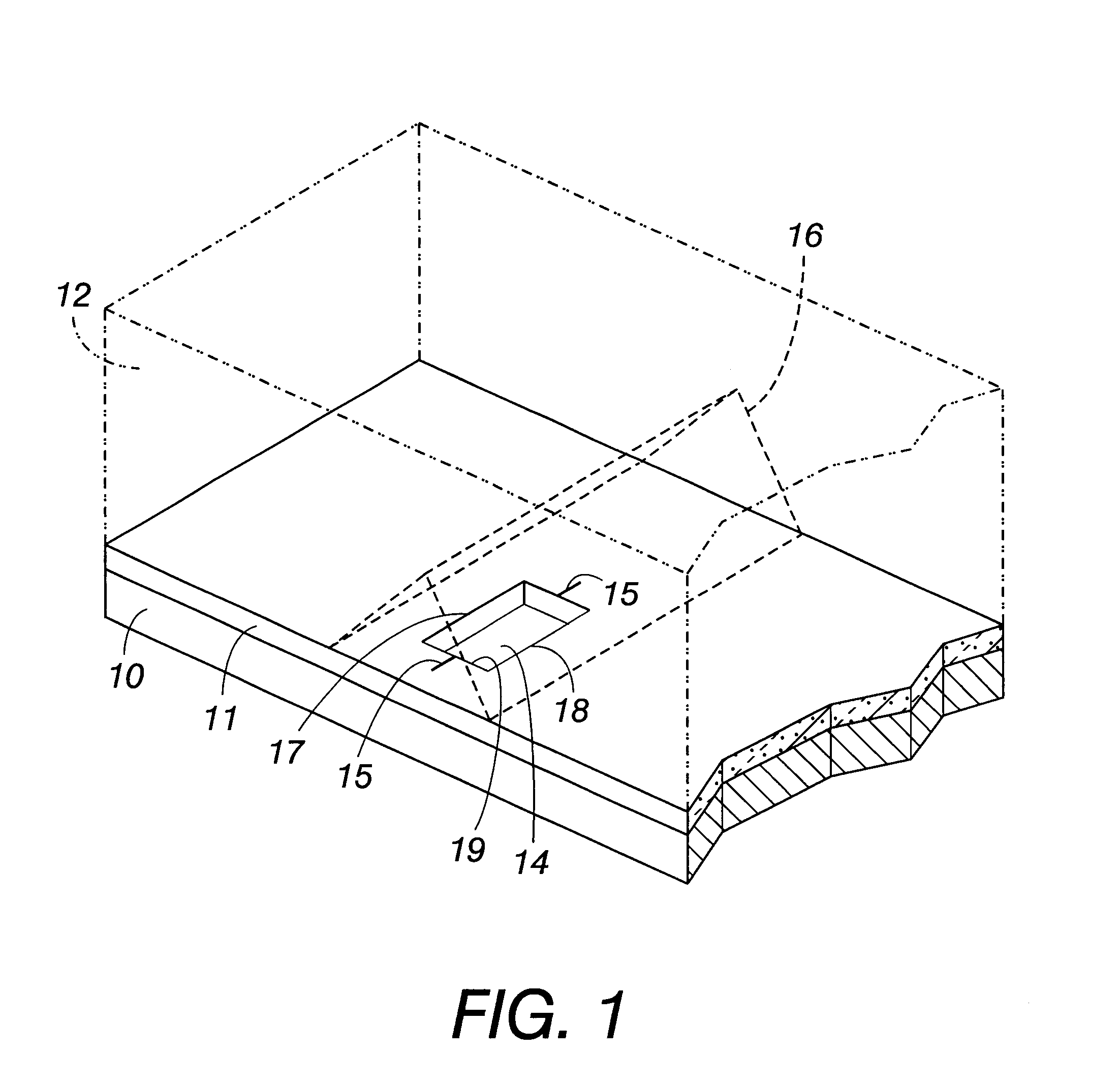
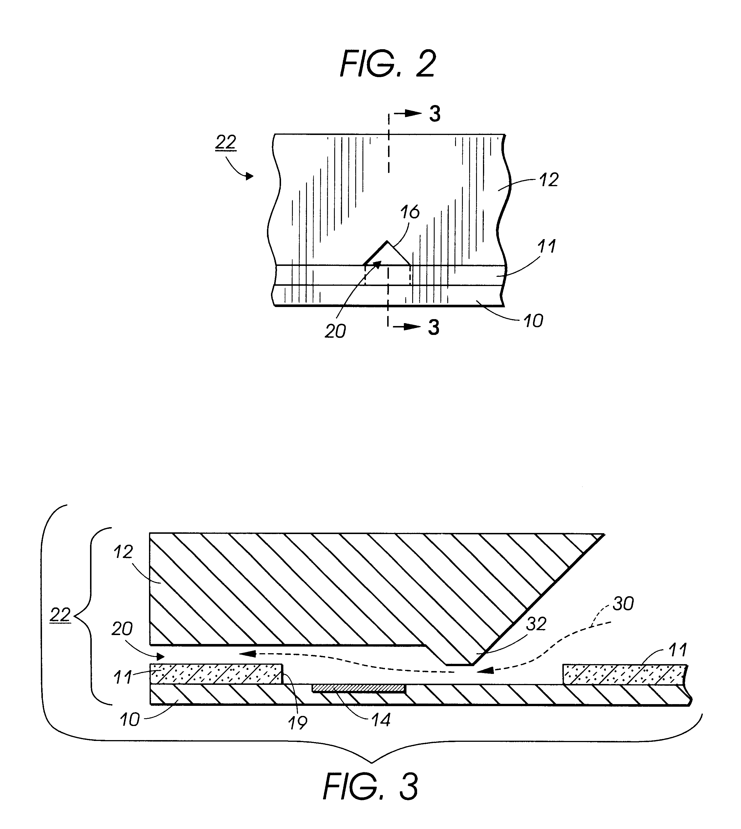
FIG. 1 is a highly simplified perspective view showing the portions of an ejector for a thermal ink jet printhead. Although only one ejector is shown, it will be understood that a practical thermal ink jet printhead will include 40 or more such ejectors, typically spaced at 300 to 1200 ejectors per inch. Illustrated in FIG. 1 is the general configuration of what is known as a "side-shooter" printhead wherein the channels forming the ejectors are created within the plane of the two pieces that form the top and the bottom of the drop ejector. The printhead comprises a heater chip 10 including a photopolymer or pit layer 11, which is in turn bound on a main surface thereof to a "channel chip" indicated in phantom as 12. The heater chip 10 is generally a semiconductor chip design as known in the art, and defines therein any number of heating elements, such as generally indicated as 14, in a pit formed in the photopolymer layer 11 with a front edge 19. There is typically provided one hea...


PUM


Abstract

An improved ink jet head wherein an ink reservoir is provided in the ink jet channel. Such a arrangement improves the printhead latency and broadens the range of inks which may be suitably utilized. In one alternative, this ink reservoir is provided between the heater and the face of the printhead and is actually an expansion of the heater pit. In another alternative, this is accomplished by shifting the forward edge of the heater pit as provided in the thick polyimide (or other photopolymer) layer found sandwiched between a heater chip and a ODE channel chip.

Description

BACKGROUND OF THE INVENTION AND MATERIAL DISCLOSURE STATEMENTThe present invention relates to a printhead for a thermal ink jet printer, and more particularly, to a thermal ink jet printer printhead with a drop ejector that uses a short plug at the front edge of a forward extended pit in the thick photopolymer layer which in combination with an orientation dependent etched (ODE) channel forms an improved nozzle therein.In thermal ink jet printing, droplets of ink are selectively ejected from a plurality of drop ejectors in a printhead. The ejectors are operated in accordance with digital instructions to create a desired image on a print sheet moving past the printhead. The printhead may move back and forth relative to the sheet in a typewriter fashion, or the linear array may be of a size extending across the entire width of a sheet, to place the image on a sheet in a single pass.The ejectors typically comprise capillary channels, or other ink passageways, which are connected to one...

Claims


Application Information

Patent Timeline
Patent Type & Authority Patents(United States)
IPC IPC(8): B41J2/14B41J2/05
CPCB41J2/1404B41J2/14145B41J2202/03B41J2002/14379
Inventor ANDREWS, JOHN R.DESHPANDE, NARAYAN V.
Owner XEROX CORP
Learn More