LED retrofit lamp with shunt capacitors across rectifier diodes for use with a ballast

a technology of rectifier diodes and retrofit lamps, which is applied in the use of semiconductor lamps, lighting and heating apparatus, semiconductor devices for light sources, etc., can solve the problems of consuming more power and generating more light, so as to reduce the power consumption, reduce the high frequency ripple, and reduce the power consumption

Active Publication Date: 2016-12-20
SIGNIFY HLDG BV
View PDF15 Cites 33 Cited by
  • Summary
  • Abstract
  • Description
  • Claims
  • Application Information

AI Technical Summary

Benefits of technology

[0019]During operation of the LED replacement lamp according to the invention, the first and second rectifiers rectify the high frequency AC voltage supplied by the high frequency fluorescent lamp ballast into a DC voltage supplying the LED load. The series arrangement of the first and second capacitor form a string that during operation conducts an AC current. As a consequence only part of the current generated by the fluorescent lamp ballast is carried by the LED load, so that the power consumed by the LED replacement lamp is lower than the power supplied by the high frequency fluorescent ballast and also lower than the nominal power of the fluorescent lamp that the high frequency fluorescent lamp ballast was designed for. As a consequence energy is saved.
[0027]Since many lamp ballasts more or less act as a constant current source, the power in the LED replacement lamp can be made lower than that of the fluorescent lamp, that the fluorescent lamp ballast was designed for by choosing the LED load voltage lower than the burning voltage of the fluorescent lamp. This way of decreasing the power in the LED replacement lamp with respect to the power consumed by the fluorescent lamp, can be used in combination with the use of the capacitors comprised in the LED replacement lamp that carry part of the current generated by the high frequency ballast, so that it does not flow through the LED load. These two mechanisms for decreasing the power consumed by the LED replacement lamp provide two degrees of freedom for fine tuning the circuitry in the LED replacement lamp.
[0028]In another preferred embodiment of a LED replacement lamp according to the invention, a first filter capacitor is coupled between the output terminals of the first rectifier and a second filter capacitor is coupled between the output terminals of the second rectifier. Both these capacitors serve to decrease the high frequency ripple present in the rectified voltage that is present across the LED load.
[0029]In yet another preferred embodiment of a LED replacement lamp according to the invention, the two lamp pins of the first lamp end circuit are connected by a first filament emulation circuit and the two lamp pins of the second lamp end circuit are connected by a second filament emulation circuit. The filament emulation circuit can simply be a resistor having similar resistance as the filament resistance of a regular fluorescent lamp. The presence of such a filament emulation circuit is necessary for some fluorescent lamp ballasts that are equipped with filament detection circuitry. Preferably, the first filament emulation circuit and the second filament emulation circuit each comprise a fusistor. In this latter case the LED replacement lamp is also effectively protected against erroneous connection of the first or second pair of lamp pins to the mains voltage directly. More preferably, the first filament emulation circuit is a series arrangement comprising two fusistors and the first rectifier contains two diodes and a common terminal of the two diodes is connected to a terminal between the two fusistors, and the second filament emulation circuit is a series arrangement comprising two fusistors and the second rectifier contains two diodes and a common terminal of the two diodes is connected to a terminal between the two fusistors. In this latter configuration, the fusistors also protect against a too high current in the LED replacement lamp.
[0032]In yet another preferred embodiment of a LED replacement lamp according to the invention the LED replacement lamp is equipped with a transparent cylindrical lamp vessel surrounding the LED load and the first and second lamp end circuit and comprises a first lamp cap equipped with the two lamp pins comprised in the first lamp end circuit and a second lamp cap equipped with the two lamp pins comprised in the second lamp end circuit. The lamp vessel and lamp caps serve to keep the LED load and the first and second lamp end circuits free from dust and dirt and therefore improve lamp life.

Problems solved by technology

When operated with an electromagnetic ballast, the lamp will generate more light but will also consume more power than when operated with a high frequency fluorescent lamp ballast.

Method used


Image

  • LED retrofit lamp with shunt capacitors across rectifier diodes for use with a ballast
  • LED retrofit lamp with shunt capacitors across rectifier diodes for use with a ballast
  • LED retrofit lamp with shunt capacitors across rectifier diodes for use with a ballast

Examples


second embodiment

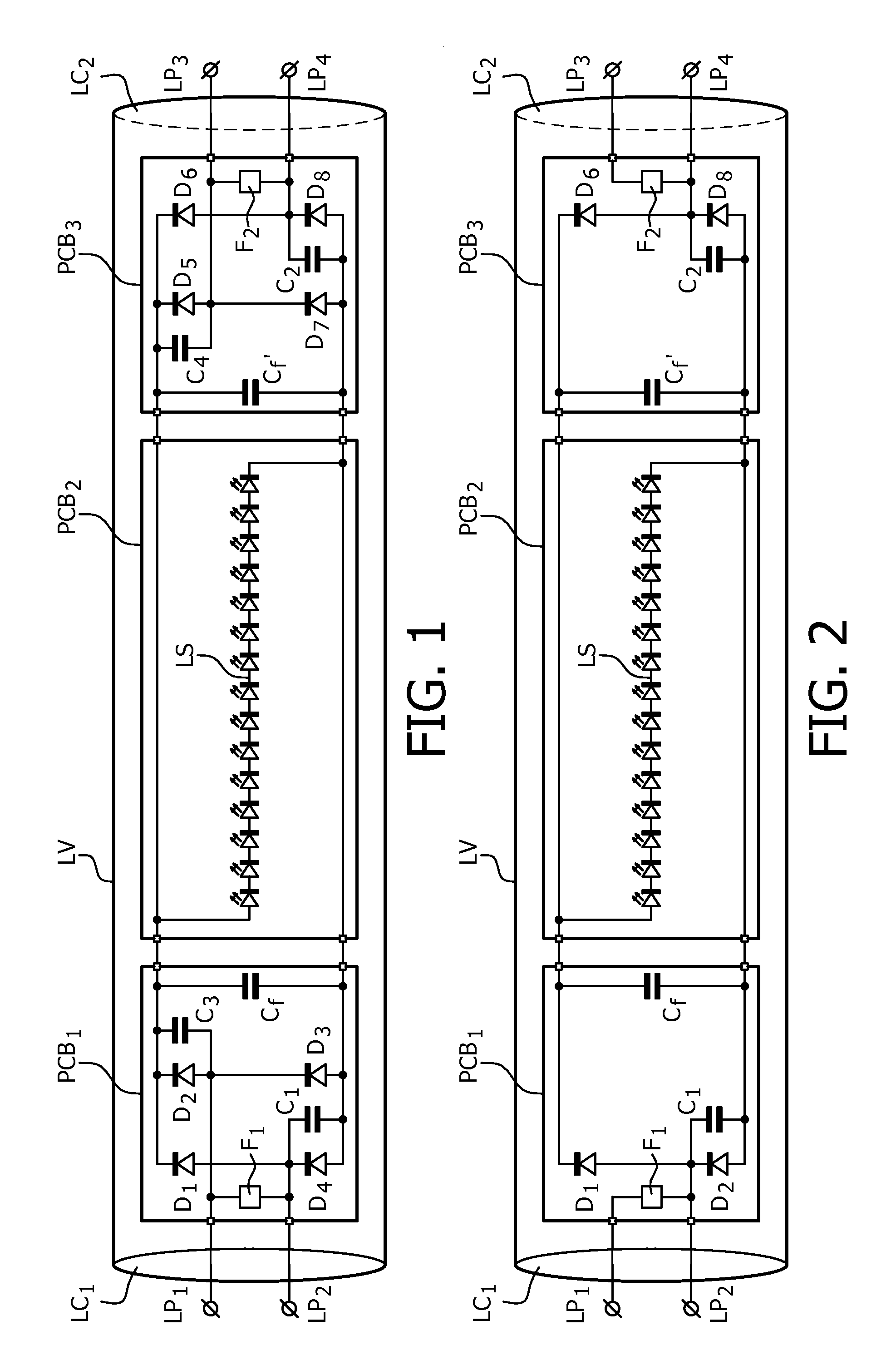
[0040]a LED replacement lamp is shown in FIG. 2. In FIG. 2 components and circuit parts corresponding to components and circuit parts comprised in the embodiment shown in FIG. 1 are labeled with the same reference signs.

[0041]A difference between the embodiment shown in FIG. 1 and the embodiment shown in FIG. 2 are that the first and second rectifiers comprised in the latter only comprise two diodes (D1, D2 and D8, D6 respectively). Furthermore only diode D2 and diode D8 are shunted by capacitor C1 and C2 respectively. Apart from filter capacitors Cf and Cf″ no other capacitors are comprised in the LED replacement lamp. The embodiment in FIG. 2 is cheaper than the one in FIG. 1 since it comprises less components.

[0042]The operation of the LED replacement lamp in FIG. 2 is very similar to the operation of the one shown in FIG. 1. A difference is that the power dissipation in the fusistors F1 and F2 may be bigger than that in the embodiment shown in FIG. 1, because for some lamp confi...

third embodiment

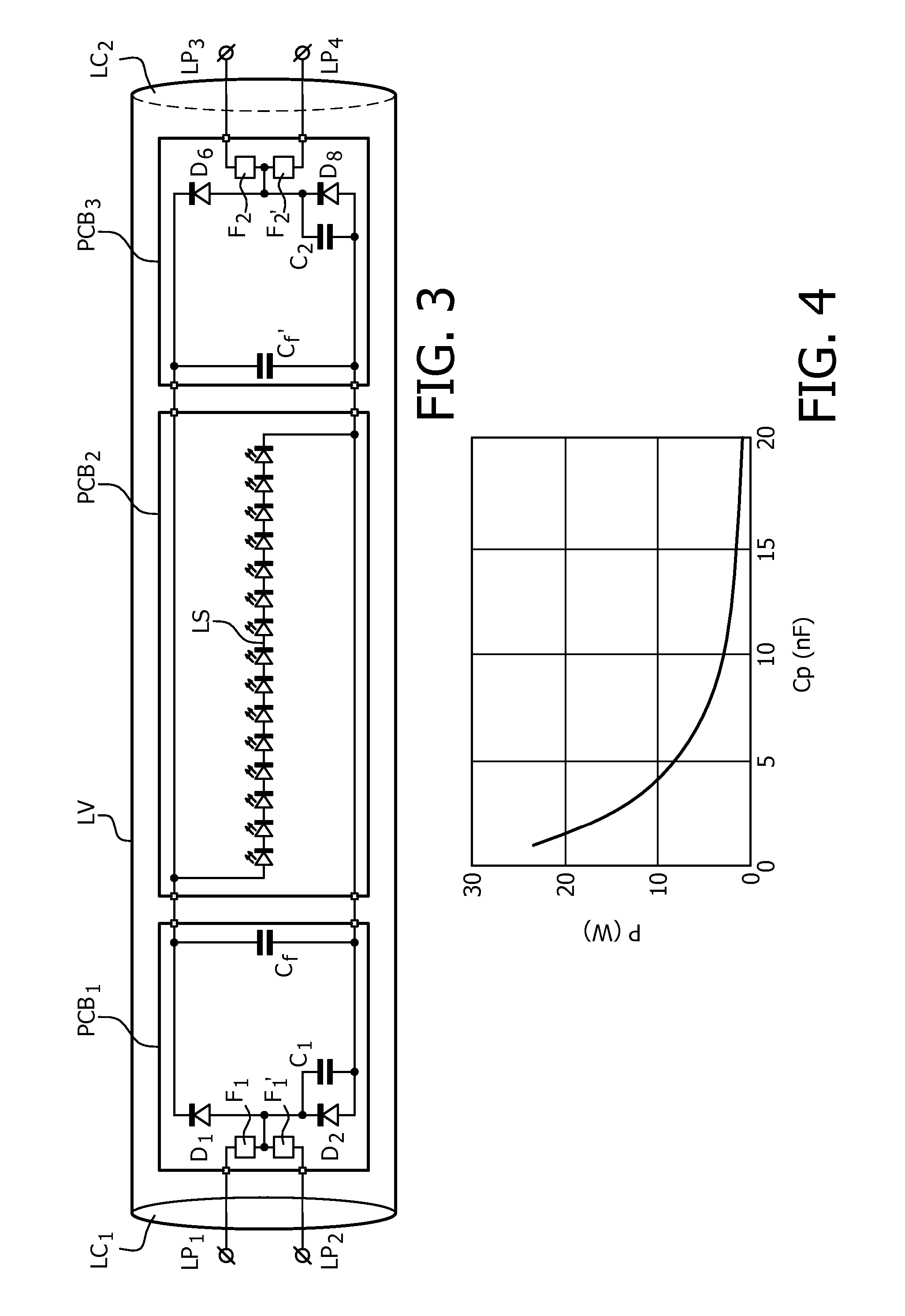
[0044]a LED replacement lamp according to the invention is shown in FIG. 3. Again the same reference signs are used for corresponding components and circuit parts.

[0045]The embodiment shown in FIG. 3 differs from the one shown in FIG. 2, in that the fusistor F1 has been replaced by a series arrangement of two fusistors F1 and F1′ and fusistor F2 has been replaced by a series arrangement of two fusistors F2 and F2′. A common terminal of fusistors F1 and F1′ is connected to a common terminal of diodes D1 and D2 and a common terminal of fusistors F2 and F2′ is connected to a common terminal of diodes D8 and D6.

[0046]The operation of the embodiment shown in FIG. 3 is very similar to that of the embodiments in FIG. 1 and FIG. 2. An important difference is that the fusistors comprised in the embodiments shown in FIG. 1 and FIG. 2 only prevent damage in case the mains voltage is directly connected between lamp pins LP1 and LP2 or between lamp pins LP3 and LP4. In the embodiment shown in FI...


PUM


Abstract

The invention relates to LED replacement lamp suitable for operation with a high frequency fluorescent lamp ballast, comprising—a LED load (LS) comprising a series arrangement of LEDs, —a first lamp end circuit comprising—a first lamp pin (LP1) and a second lamp pin (LP2) for connection to a first lamp connection terminal comprised in the high frequency fluorescent lamp ballast, —a first rectifier (D1-D4; D1, D2) equipped with at least one input terminal coupled to the second lamp pin and with first and second output terminals coupled to respective ends of the LED load, the first rectifier comprising at least two diodes, one of which is shunted by a first capacitor (C1), —a second lamp end circuit comprising—a third lamp pin (LP3) and a fourth lamp pin (LP4) for connection to a second lamp connection terminal comprised in the high frequency fluorescent lamp ballast, —a second rectifier (D5-D8, D5, D6) equipped with at least one input terminal coupled to the fourth lamp pin and with first and second output terminals coupled to respective ends of the LED load, the second rectifier comprising at least two diodes, one of which is shunted by a second capacitor (C2), wherein the first capacitor and the second capacitor form a series arrangement coupled between the second lamp pin and the fourth lamp pin.

Description

CROSS-REFERENCE TO PRIOR APPLICATIONS[0001]This application is the U.S. National Phase application under 35 U.S.C. §371 of International Application No. PCT / IB2013 / 051444, filed on Feb. 22, 2013, which claims the benefit of U.S. Patent Application No. 61 / 602,710, filed on Feb. 24, 2012. These applications are hereby incorporated by reference herein.FIELD OF THE INVENTION[0002]The invention relates to a LED replacement lamp that is suitable for operation with a fluorescent lamp ballast, more in particular with a high frequency fluorescent lamp ballast. The LED replacement lamp is equipped with lamp pins, like a fluorescent lamp so that it can be directly coupled to the fluorescent lamp ballast.BACKGROUND OF THE INVENTION[0003]Fluorescent lamps have been a very successful light source. They are used on a huge scale. In fact more than 60% of the artificial light is generated by fluorescent lamps today. However, in recent years LED lighting technology has been rapidly developed and repl...

Claims


Application Information

Patent Timeline
Patent Type & Authority Patents(United States)
IPC IPC(8): H05B37/00H05B33/08F21K99/00H05B37/02F21V23/00H05B44/00
CPCH05B33/0809F21K9/27F21V23/005H05B33/08H05B37/02F21K9/278Y02B20/30H05B45/3578H05B44/00
Inventor TAO, HAIMINJANS, WILLIAM PETER MECHTILDIS MARIE
Owner SIGNIFY HLDG BV
Why Eureka
Try Eureka