
Dental post and method for its fabrication

a technology of dental posts and resin matrix, applied in the field of dental posts, can solve the problems of limited material choice for resin matrix materials, limited light conduction through fibers, and unsuitable materials with low transparency, and achieve good optical properties, and good light conduction properties

Active Publication Date: 2016-12-27
NORDIN HARALD +1
View PDF36 Cites 0 Cited by
  • Summary
  • Abstract
  • Description
  • Claims
  • Application Information

AI Technical Summary

Benefits of technology

The present invention aims to provide a dental post that has good optical properties, including light conduction and emission over a large surface area, while keeping limitations on the choice of resin material low. The dental post should also have high radiopacity and photochromic properties, as well as good retention properties. The invention provides a method for fabricating such a dental post.

Problems solved by technology

Thus, the choice of material for the resin matrix depends on its good light conduction properties and favorable materials with low transparency may not be applicable.
This, however, restricts the choice of available materials for the resin matrix.
Thus, light conduction through the fibers is only possible between the two end points of the dental device and no light can be extracted from the lateral surface of the dental post.
A disadvantage of this dental post is that no retention means are provided in order to secure the position of the post within the root canal.
A further drawback of this dental post is that the exploitation of the resin matrix as a light conductor not only restricts the choice of a preferred X-ray absorbing material in order to avoid the scattering of light rays, but also leads more generally to a certain loss that is related to light diffusion occurring in the resin matrix.
Furthermore, the narrow spacing between adjacent circumferential cycles of the single thread may lead to a large rate of scattering or diffusion of light if applied to a light conducting dental post.

Method used


Image

  • Dental post and method for its fabrication
  • Dental post and method for its fabrication
  • Dental post and method for its fabrication

Examples


Embodiment Construction

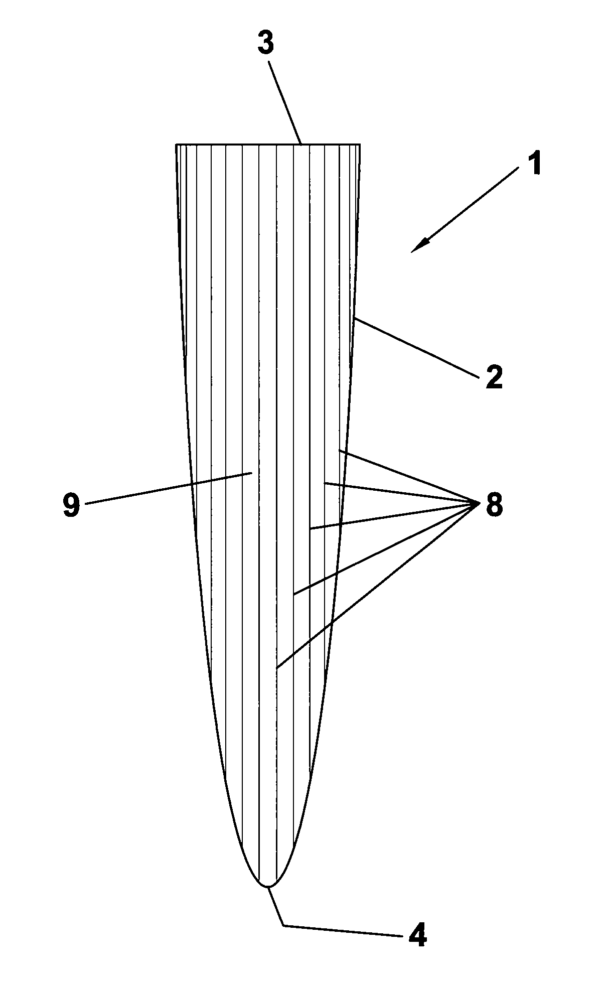
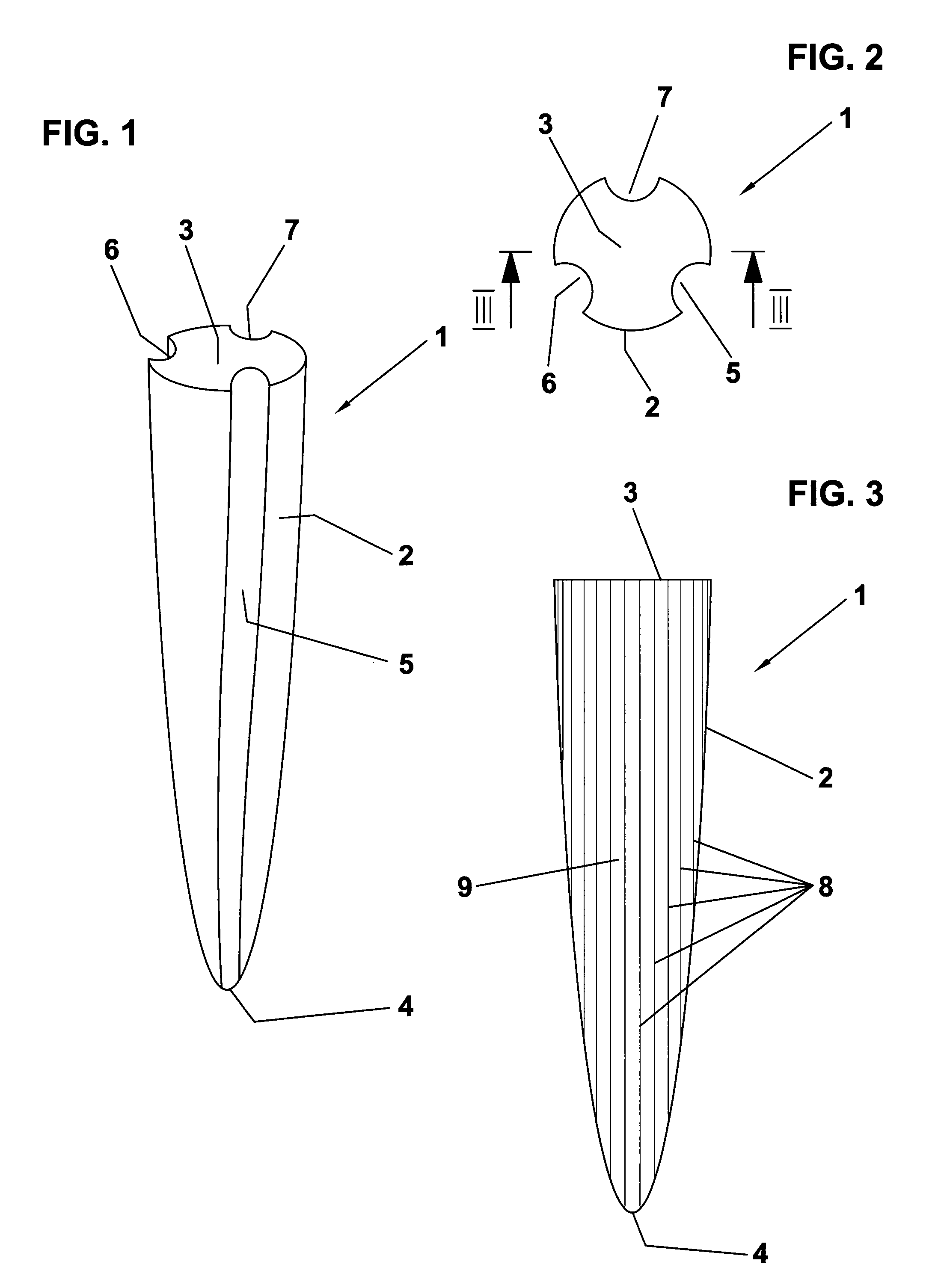
[0044]FIGS. 1 to 3 depict a dental post 1 according to an embodiment of the invention. According to the perspective view shown in FIG. 1 and the front view illustrated in FIG. 2, the dental post 1 comprises a circumferential surface 2 with a longitudinal taper extending from the first end 3 to the second end 4 of the post 1. The course of the taper is determined by a continously increasing slope towards the second end 4. With respect to terms commonly used in dentistry, the first end 3 corresponds to the coronal end and the second end 4 corresponds to the apical end of the dental post.

[0045]Three grooves 5, 6, 7 have been formed in the circumferential surface 2, which are longitudinally extending over the total length of the post 1 and twisted along the circumference of the surface 2. Thus, each groove 5, 6, 7 extends approximately over one third of the circumference of the surface 2 along a helical course. The grooves 5, 6, 7 are equally distributed around the surface 2, such that ...


PUM

PropertyMeasurementUnit
atomic numberaaaaaaaaaa
sizeaaaaaaaaaa
sizeaaaaaaaaaa

Abstract

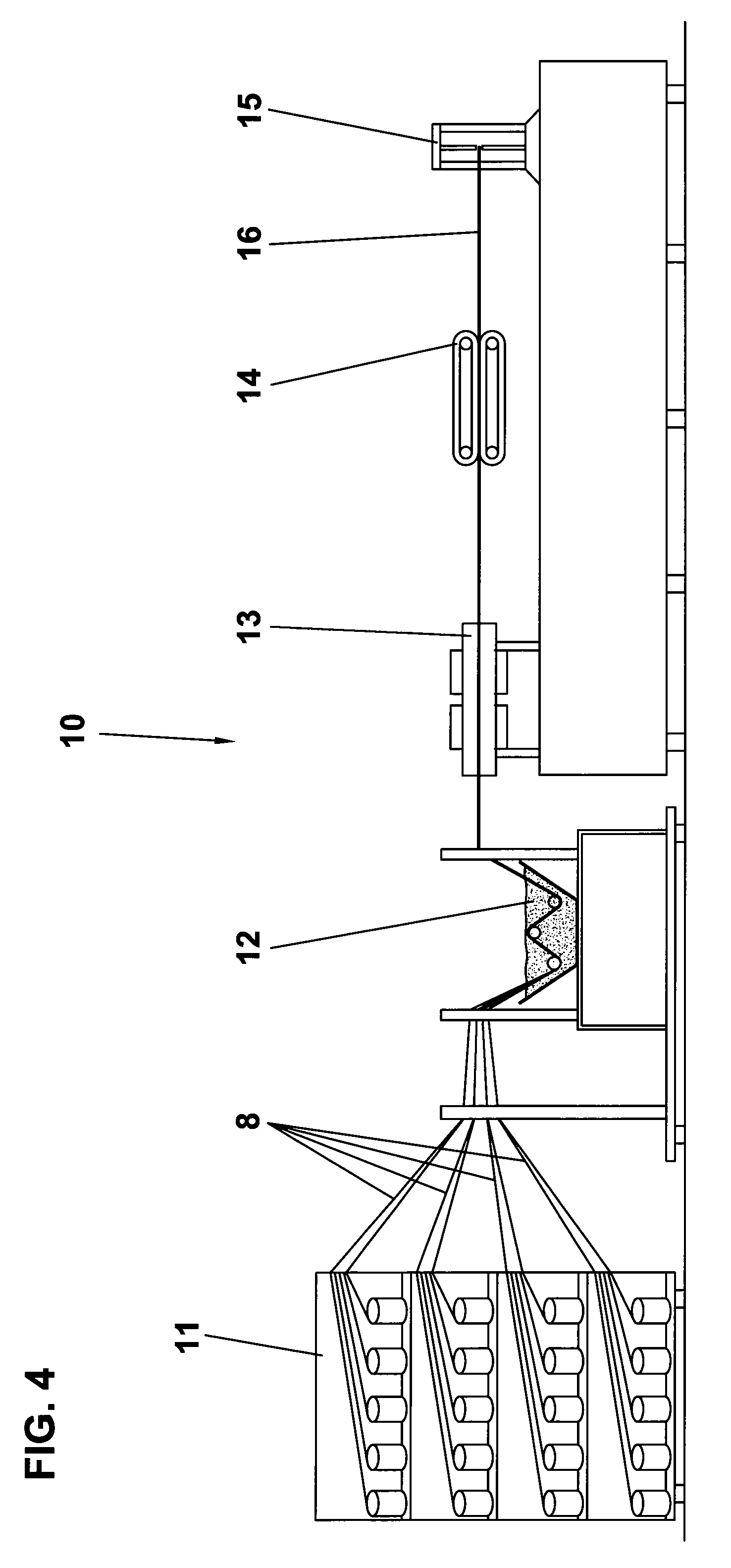
A dental post consisting of fiber-reinforced material with substantially uniformly directed fibers and mountable in a tooth root canal for fixing a dental prosthetic structure on a tooth stump and a method for its fabrication.For improving the light conduction properties within the post, at least a fraction of said fibers are adapted for light conduction within said post and said post comprises a tapered portion extending towards its second end, wherein at least a fraction of said light conducting fibers extend from the first end of said post to the circumferential surface of said tapered portion.An advantageous fabrication method of the dental post comprises forming of a composite structure of uniform cross-section with substantially uniformly directed light conducting fibers in a pultrusion process and shaping of at least a portion of the circumferential surface of said composite structure in order to provide a tapered portion extending towards the second end of said composite structure.

Description

FIELD OF THE INVENTION[0001]The invention relates to a dental post consisting of fibre-reinforced material with substantially uniformly directed fibers and mountable in a tooth root canal for fixing a dental prosthetic structure on a tooth stump. The invention further relates to a method for fabricating a dental post consisting of fibre-reinforced material.BACKGROUND OF THE INVENTION[0002]U.S. Pat. No. 5,919,044 discloses a flexible dental post comprising a bundle of optical fibers that are uniformly directed and twisted in a non-axial arrangement in order to impart additional strength to the dental post. The fiber bundle is embedded in a resin binder and extends from the apical end to the coronal end of the post. In this way, light can be guided in between the two end points of the post. In addition, a transverse light conduction towards the circumferential surface of the post can be achieved by etching or scoring the coating of the fibers yielding several light leakage points alon...

Claims


Application Information

Patent Timeline
Patent Type & Authority Patents(United States)
IPC IPC(8): A61C1/07A61C3/03B29C70/52A61C3/08A61C13/30B29C70/54A61C5/00A61C5/30B29L31/00
CPCA61C13/30B29C70/52B29C70/545B29L2031/7536A61C13/20A61C19/04
Inventor NORDIN, HARALDNORDIN, PETER
Owner NORDIN HARALD
Learn More