Watercraft lift and automatic watercraft cover

a technology for watercraft and covers, applied in the direction of roofs, vessel construction, transportation and packaging, etc., can solve the problems of difficult installation of covers, large covers, and time-consuming installation of covers

Active Publication Date: 2016-12-27
SUNSTREAM CORP
View PDF21 Cites 11 Cited by
  • Summary
  • Abstract
  • Description
  • Claims
  • Application Information

AI Technical Summary

Problems solved by technology

The large number of snaps or other fasteners used make the covers time consuming to install.
The covers are often difficult to install after the material ages.
The covers are large and awkward to store on-board.
The covers can be dirty, and unpleasant to handle.
The covers tend to lose shape, causing pockets of water, which further cause a loss of shape and pools of water.
The covers do not cover a significant amount of hull surface surrounding the covers, and do not cover significant portions of the sides of the boat with which used, which causes fading in the sun and does not protect these areas from dirt.
The covers provide no security, which makes the contents of the boat and the boat itself vulnerable to theft.
This design would not be ideal for use with a boat lift since the cover is two-dimensional, non-adjustable and would be impractical to fit the three-dimensional shapes of various boat types with which the lift might be used.
The torsional spring of the roller is also subject to over-tightening.
Such a design does not provide protection to the sides of the boat.
It also is more vulnerable to side wind, since it has exposed edges that catch the wind.
This type of design is undesirable for an application on a boat, since the cover slides over parts of the boat, causing cover wear, and potential boat damage.
The fixed cover in the front also blocks views and is not attractive since the roller remains visible at the front even when the cover is deployed.
Pulling the cover from a fixed roller in the front also can cause damage to the cover and boat by dragging the cover on the boat.
Further, the lift with the cover similar to that described in U.S. Pat. No. 3,549,198 does not provide any protection against operation of the lift when the cover is deployed, which can cause cover or boat damage, especially if installed on lifts that translate rearward when lowering, such as the lift of U.S. Pat. No. 5,908,264.
Since the lift of this patent with the cover similar to U.S. Pat. No. 3,549,198 does not use the same remote control, another drawback is that the user is required to operate it separately from the automatic boat cover.
The tall sides of these systems block views and are more vulnerable to wind.
For use on a free-standing boat lift, the fixed roof structure can make the lift vulnerable to tipping.
The design is not conducive to covering the full sides of the watercraft.
U.S. Pat. No. 8,911,174 solves the challenges above, but did not address some additional challenges.
This adjustment is complicated since an adjustment impacts both the forward and rear position at the same time.
These adjustments are made underwater, making adjustments even more challenging.
Since more cover tension can be perceived as beneficial, the operator can over tension the torsion spring and cause spring damage.
The automatic boat cover of U.S. Pat. No. 8,911,174 is costly, largely due to the hydraulic and control systems.
Applying U.S. Pat. No. 8,911,174 to a boat lift with a lifting cradle, lifted by cables, is challenging since the pivot position under the boat may limit minimum water depth.
The design of this cover is difficult for some boats that have protruding features such as antennas and / or fishing gear.

Method used


Image

  • Watercraft lift and automatic watercraft cover
  • Watercraft lift and automatic watercraft cover
  • Watercraft lift and automatic watercraft cover

Examples


Embodiment Construction

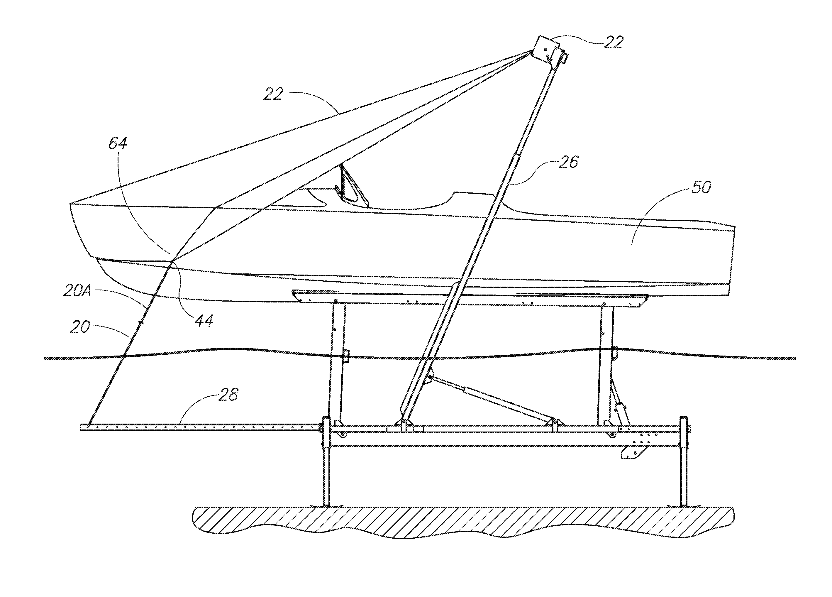
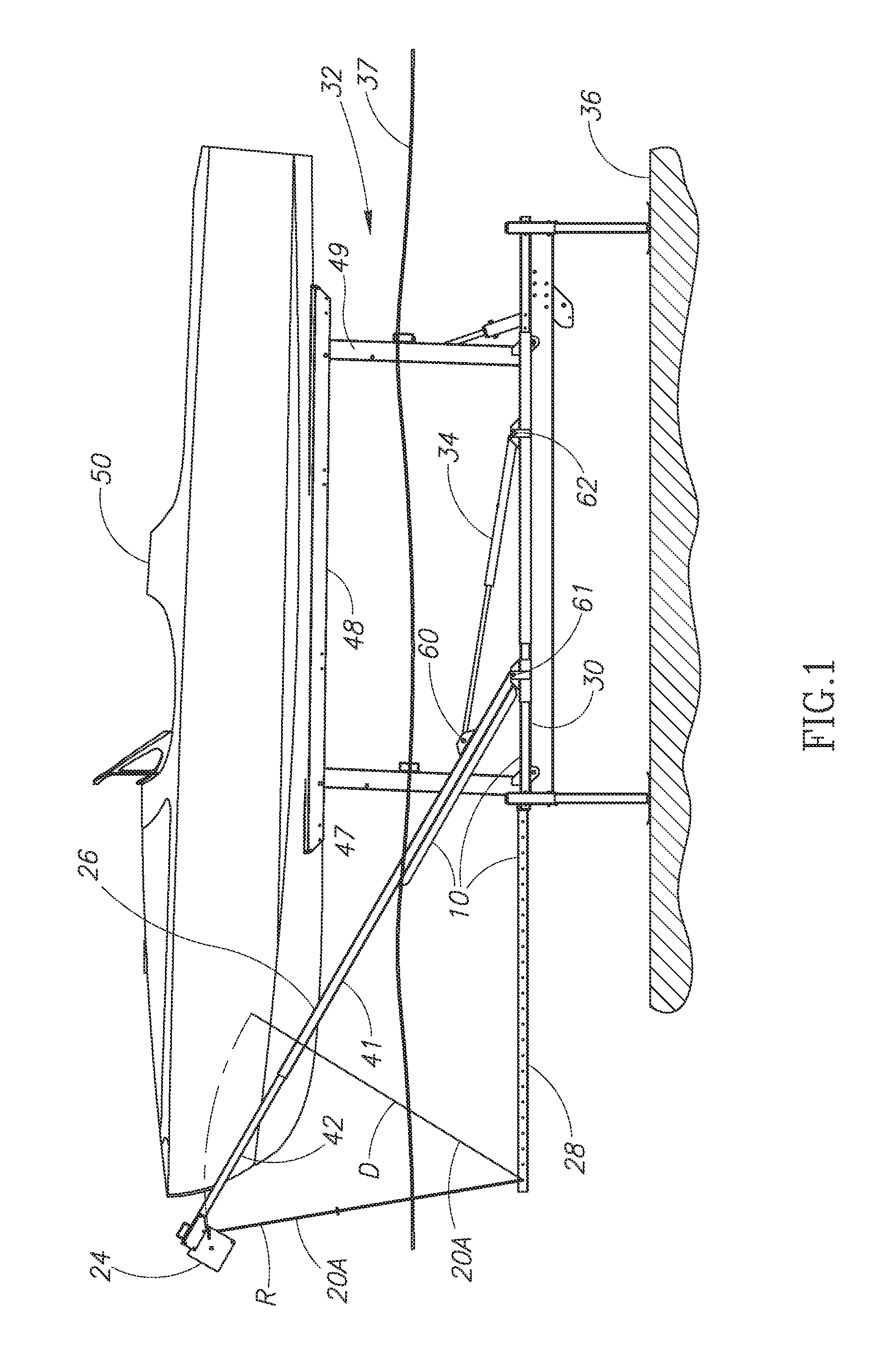
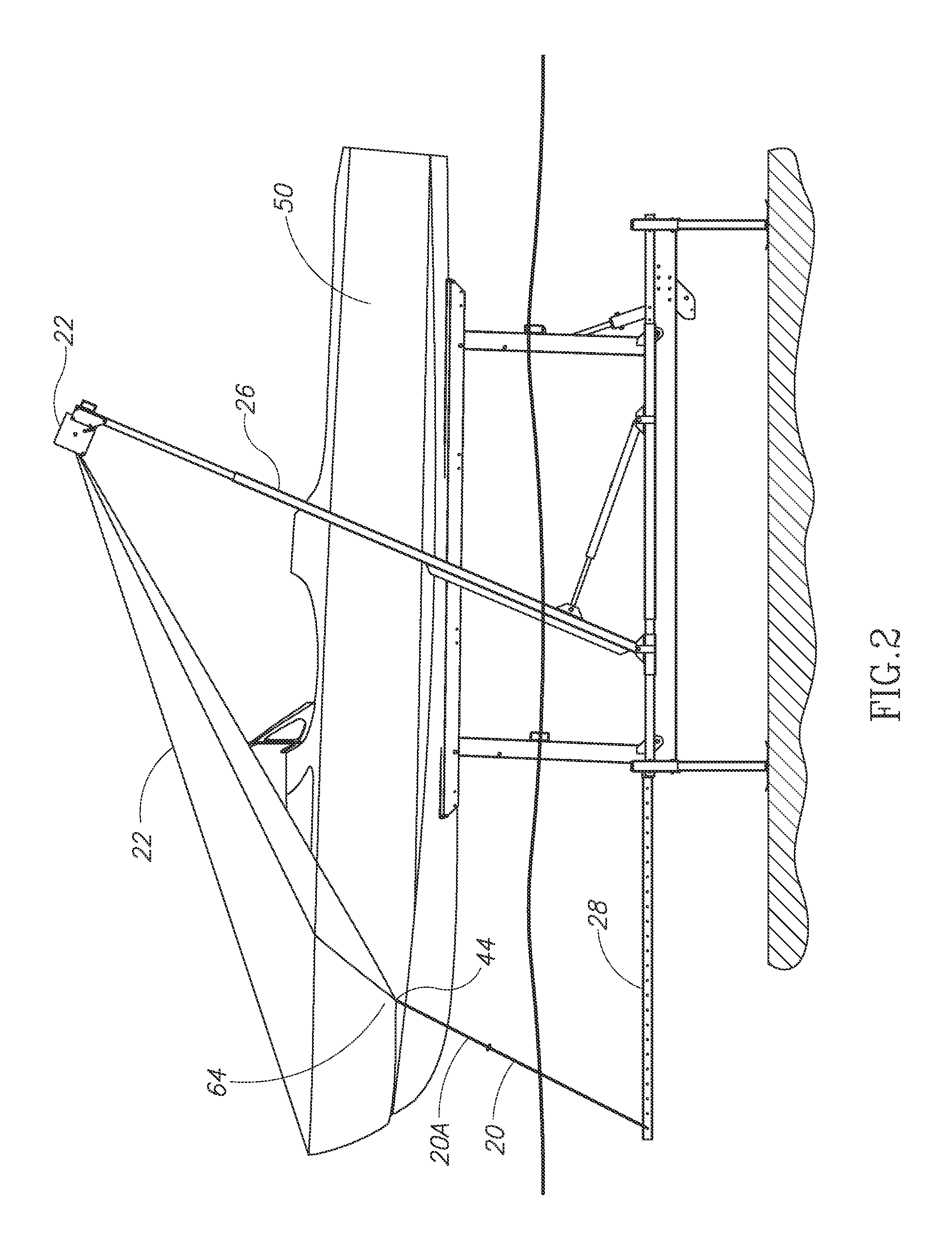
[0040]The invention generally relates to a watercraft lift system generally used for lifting powerboats under 30 feet long, however, the design could be applied to other type boat and watercraft lift systems and other type boats and watercraft. U.S. Pat. No. 8,911,174 is incorporated herein by reference in its entirety.

[0041]The disclosed embodiments of the invention are illustrated for a watercraft lift system that allows for simple installation and removal of the cover, better protection for the boat or other watercraft being lifted, less view blockage, and better theft prevention. The combination of these features saves the boater time before and after boating, reduces hull cleaning, reduces hull fading, and allows the owner to store equipment, such as water skis inside the boat more securely.

[0042]According to the watercraft lift system disclosed herein, one may set the forward swing arm angle by fully extending the hydraulic cylinder, and fine-tune the swing arm angle by changi...


PUM


Abstract

A boat lift with hydraulically or mechanically actuated arms which self-installs a fitted three-dimensional boat cover on a powerboat. The control logic of the system allows for cover operation only when the lift is raised. A spring-tensioned roller keeps the cover tight and self-rolls the cover on the roller when the actuated arms are pivoted forward. The roller is hidden behind the boat in ‘cover-on’ position. A slip clutch prevents the torsion spring from being over tightened. The forward position of the roller is adjusted by adjusting the hydraulic cylinder length. The rearward position of the roller is adjusted by limiting the retracted position of the hydraulic cylinder. A non-hydraulic embodiment actuates the cover when the lift is operated.

Description

CROSS REFERENCE TO RELATED APPLICATION(S)[0001]This application claims the benefit of U.S. Provisional Patent Application No. 61 / 991,214 filed May 9, 2014.BACKGROUND OF THE INVENTION[0002]Field of the Invention[0003]The present invention relates to free-standing and other watercraft lifts and watercraft covers for use with watercraft lifts.[0004]Description of the Related Art[0005]The use of boat covers to protect boats is well known. A number of designs are currently known to perform this basic operation. Many boats have multi-section covers, often with one covering the bow section and another covering the aft section. The covers are typically shaped to cover at least portions of the three-dimensional shape of a boat and are manually spread out over the boat and then manually attached using snap or other fasteners. The bow section is attached with fasteners around the perimeter of the bow section especially when there is a bow opening. The aft section is attached to fasteners on th...

Claims


Application Information

Patent Timeline
Patent Type & Authority Patents(United States)
IPC IPC(8): B63B17/02B63C3/06E04F10/02B63C3/12
CPCB63B17/02B63C3/06B63C3/12E04F10/02B60J7/085E04F10/0651E04F10/0659
Inventor HEY, KENNETH EDWARDSSTANFORD, DEAN ALLENHALVERSON, LOERN
Owner SUNSTREAM CORP
Why Eureka
Try Eureka