Control system for work vehicle, control method, and work vehicle

Inactive Publication Date: 2016-12-27
KOMATSU LTD
View PDF25 Cites 1 Cited by
  • Summary
  • Abstract
  • Description
  • Claims
  • Application Information

AI Technical Summary

Benefits of technology

This patent aims to allow work vehicles to carry on working without becoming overheated. The invention helps limit this problem, ensuring the vehicle's electrical drive system is always cool and functioning properly.

Problems solved by technology

There is a concern in the hybrid-type work vehicle that when the output of the electric motor increases, the temperature of the electrical drive system including the electric motor may rise and overheat.
However, work cannot be continued if the electric motor is shut down when the output of the electric motor becomes large.
Moreover, the output of the electric motor is limited without completely stopping the electric motor.
The controller may continue the limitation of the output of the electric motor when the operating member for the movable body is being operated even when the temperature of the electrical drive system falls below the release threshold during the limitation of the output of the electric motor.
Moreover, the output of the electric motor can be limited by switching the control mode to the first control mode when the temperature of the electrical drive system exceeds the first threshold while executing the second control mode.
Moreover, the output of the electric motor can be limited in the first control mode in comparison to the second control mode.
Moreover, the output of the electric motor is limited without completely stopping the electric motor.
The limitation of the output of the electric motor is not performed when the operating unit of the movable body is being operated even when the temperature of the electrical drive system exceeds the first threshold.
Moreover, the output of the electric motor is limited without completely stopping the electric motor.

Method used


Image

  • Control system for work vehicle, control method, and work vehicle
  • Control system for work vehicle, control method, and work vehicle
  • Control system for work vehicle, control method, and work vehicle

Examples


Embodiment Construction

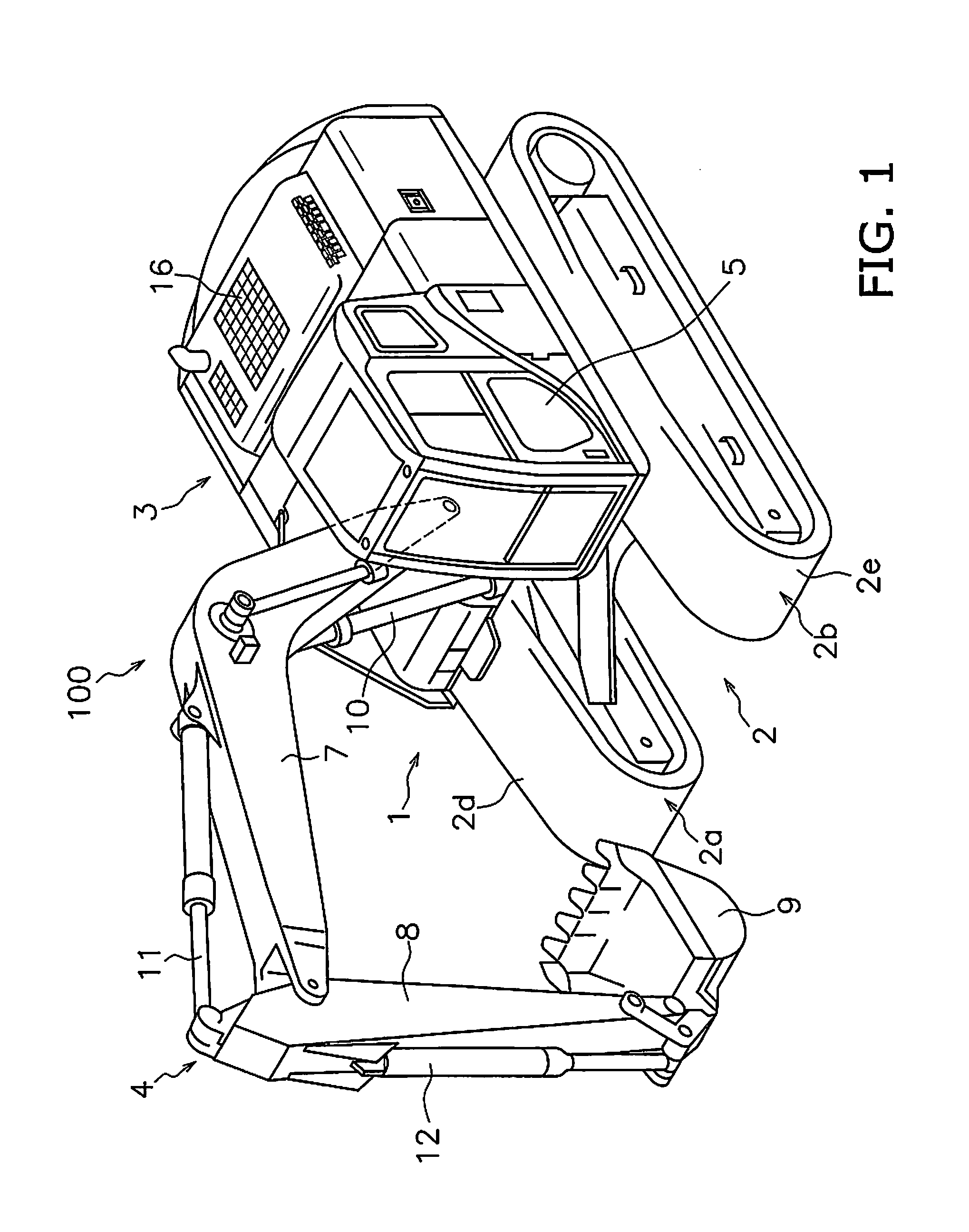
[0035]The following is a description of a work vehicle according to the present exemplary embodiment with reference to the drawings. FIG. 1 is a perspective view of a work vehicle 100 according to an exemplary embodiment. The work vehicle 100 is a hydraulic excavator according to the present exemplary embodiment. The work vehicle 100 is provided with a vehicle body 1 and a work implement 4.

[0036]The vehicle body 1 includes a traveling body 2 and a revolving body 3. The traveling body 2 includes a pair of travel devices 2a and 2b. The travel devices 2a and 2b respectively include crawler belts 2d and 2e. The travel devices 2a and 2b drive the crawler belts 2d and 2e enabling the work vehicle 100 to travel.

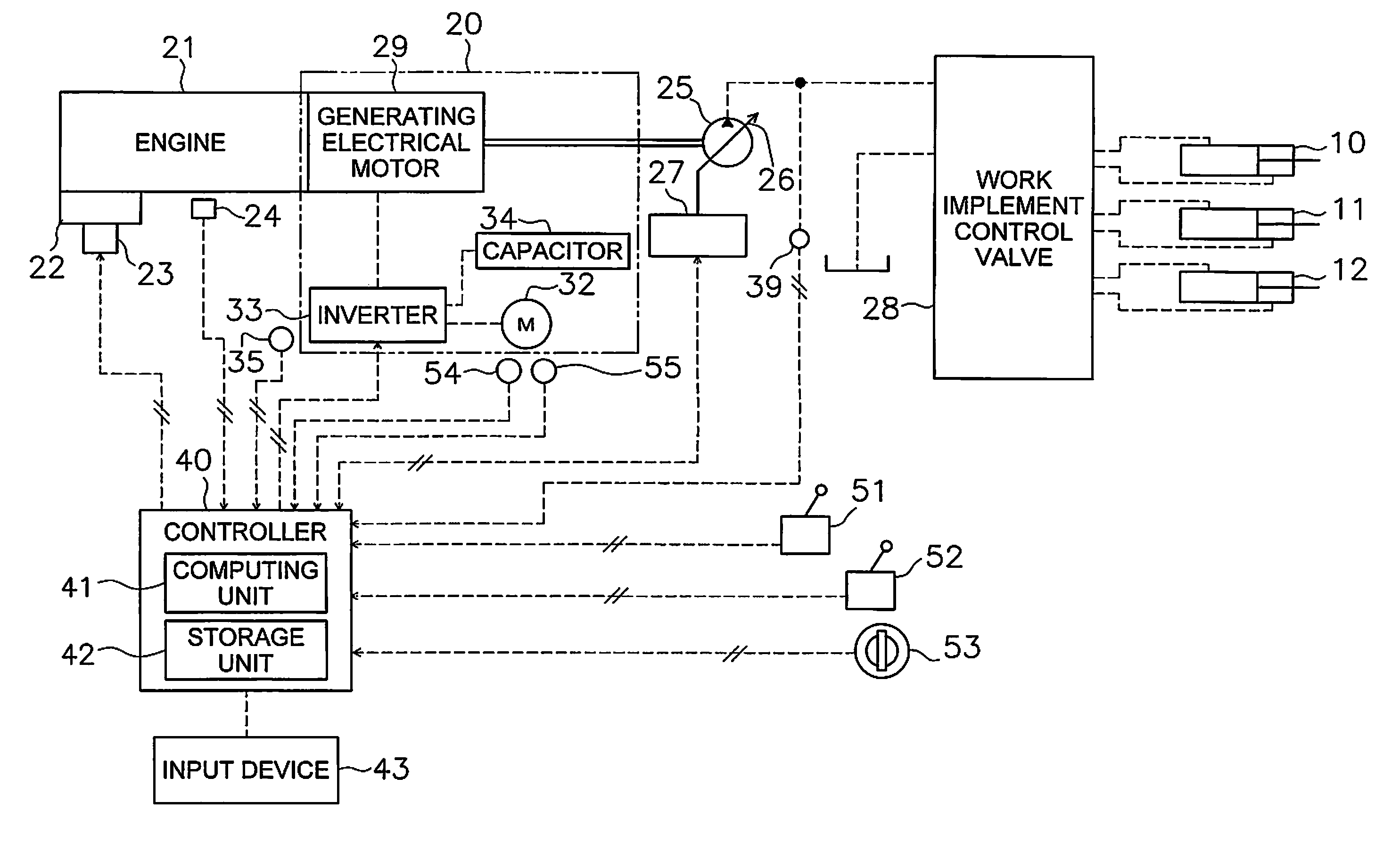
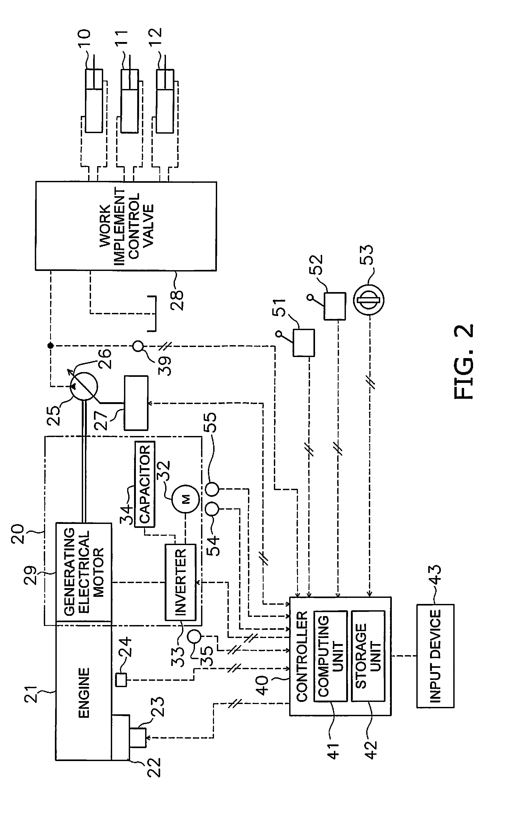
[0037]The revolving body 3 is mounted on the traveling body 2. The revolving body 3 is provided in a rotatable manner with respect to the traveling body 2. The revolving body 3 turns by being driven by a below-mentioned revolving electric motor 32 (see FIG. 2). A cab 5 is provided i...


PUM


Abstract

A control system for a work vehicle includes a temperature detecting unit and a controller. The temperature detecting unit detects the temperature of the electrical drive system. The controller controls the output of an electric motor when the temperature of the electrical drive system detected by the temperature detecting unit exceeds a predetermined first threshold and an operating member of the movable body is positioned in a neutral position. The controller does not limit the output of the electric motor when the operating member for the movable body is being operated even when the temperature of the electrical drive system exceeds the first threshold.

Description

CROSS-REFERENCE TO RELATED APPLICATIONS[0001]This application is a U.S. National stage application of International Application No. PCT / JP2015 / 080909, filed on Nov. 2, 2015.BACKGROUND[0002]Field of the Invention[0003]The present invention relates to a control system for a work vehicle, a control method, and a work vehicle.[0004]Background Information[0005]A work vehicle includes a movable body, such as a revolving body. For example, the work vehicle in Japanese Laid-open Patent No. 2010-285828 is equipped with a hydraulic pump and a hydraulic motor. The revolving body of the work vehicle of Japanese Laid-open Patent No. 2010-285828 is turned by driving the hydraulic motor using hydraulic fluid discharged from the hydraulic pump.[0006]However, hybrid-type work vehicles have recently been developed which are equipped with an electric motor instead of the hydraulic motor as in Japanese Patent No. 5044727. The revolving body is turned using an electric motor in the hybrid-type work vehi...

Claims


Application Information

Patent Timeline
IPC IPC(8): G06F7/70E02F9/22H02P29/00H02K9/04E02F9/20E02F9/08E02F3/32
CPCE02F9/2095E02F9/0841E02F9/2075E02F9/226E02F9/0866E02F9/2235H02P29/0044H02K9/04E02F3/32Y10S903/903B60Y2200/412H02P29/60
Inventor KAMADO, MITSUHIKO
Owner KOMATSU LTD
Why Eureka
Try Eureka