
Anti-rotation handguard system

a handguard and anti-rotation technology, which is applied in the field of anti-rotation system of firearm handguards, can solve the problems of difficult to keep the handguard from rotating relative to the upper receiver of the firearm on which the handguard is installed, and achieve the effect of ensuring the installation or removal of the handguard

Active Publication Date: 2016-12-27
OGLESBY PAUL
View PDF66 Cites 57 Cited by
  • Summary
  • Abstract
  • Description
  • Claims
  • Application Information

AI Technical Summary

Benefits of technology

The patent describes a system that allows a user to easily install or remove a handguard on a firearm. It prevents the handguard from spinning or getting stuck.

Problems solved by technology

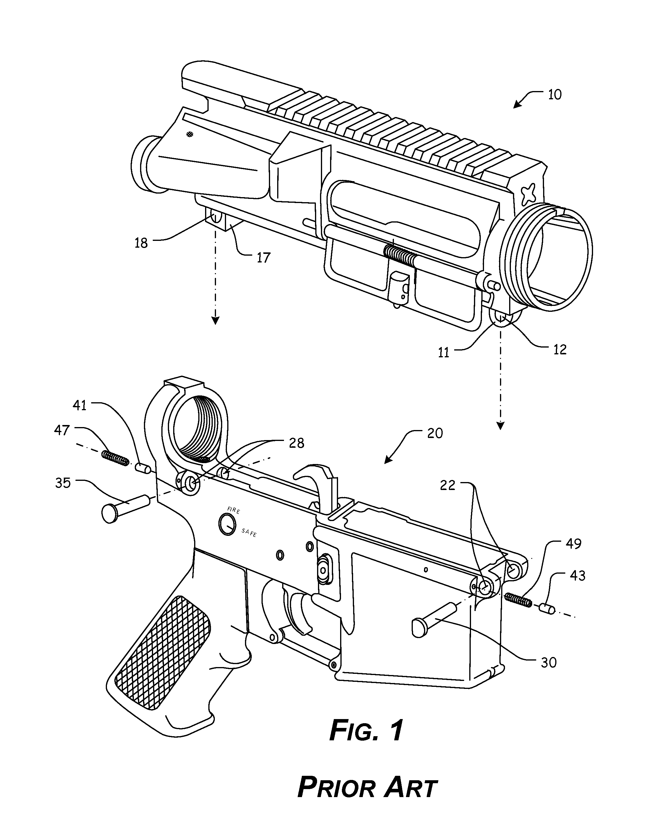
For example, when rotational torque is placed on a typical handguard, it is difficult to keep the handguard from rotating relative to the upper receiver of the firearm on which the handguard is installed.

Method used


Image

  • Anti-rotation handguard system
  • Anti-rotation handguard system
  • Anti-rotation handguard system

Examples


Embodiment Construction

[0084]For simplicity and clarification, the design factors and operating principles of the anti-rotation handguard system according to this invention are explained with reference to various exemplary embodiments of an anti-rotation handguard system according to this invention. The basic explanation of the design factors and operating principles of the anti-rotation handguard system is applicable for the understanding, design, and operation of the anti-rotation handguard system of this invention. It should be appreciated that the anti-rotation handguard system can be adapted to many applications where an attachment / anti-rotation system can be used.

[0085]As used herein, the word “may” is meant to convey a permissive sense (i.e., meaning “having the potential to”), rather than a mandatory sense (i.e., meaning “must”). Unless stated otherwise, terms such as “first” and “second” are used to arbitrarily distinguish between the elements such terms describe. Thus, these terms are not necess...


PUM


Abstract

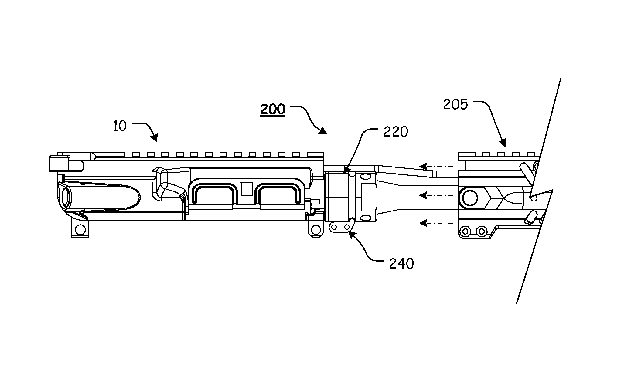
An anti-rotation handguard system, including a barrel nut having a barrel nut aperture formed therethrough, along a longitudinal axis of the barrel nut, wherein the barrel nut includes a registration groove defined around the outer periphery of the barrel nut; and an anti-rotation ring having a barrel nut aperture formed therethrough, wherein the anti-rotation ring further comprises a first anti-rotation tab extending from the anti-rotation ring, wherein the first anti-rotation tab is formed so as to be received within a gas tube channel of a handguard, and wherein the anti-rotation ring further comprises a second anti-rotation tab extending from the anti-rotation ring, wherein the second anti-rotation tab is formed so as to be received within at least a portion of a compression / registration slot of the handguard.

Description

CROSS-REFERENCE TO RELATED APPLICATIONS[0001]This patent application claims the benefit of U.S. Patent Application Ser. No. 62 / 066,142, filed Oct. 20, 2014, the entire disclosure of which is incorporated herein by reference. This patent application is a Continuation-In-Part of U.S. patent application Ser. No. 14 / 709,025, filed May 11, 2015, which claims the benefit of U.S. Patent Application Ser. No. 61 / 991,401, filed May 9, 2014, the entire disclosures of which are incorporated herein by reference.STATEMENT REGARDING FEDERALLY SPONSORED RESEARCH OR DEVELOPMENT[0002]Not Applicable.REFERENCE TO SEQUENCE LISTING, A TABLE, OR A COMPUTER PROGRAM LISTING COMPACT DISC APPENDIX[0003]Not Applicable.NOTICE OF COPYRIGHTED MATERIAL[0004]The disclosure of this patent document contains material that is subject to copyright protection. The copyright owner has no objection to the reproduction by anyone of the patent document or the patent disclosure, as it appears in the Patent and Trademark Offic...

Claims


Application Information

Patent Timeline
IPC IPC(8): F41C23/00F41C23/16
CPCF41C23/16F41A21/482F41G11/003F41A21/48F41C23/00F41C27/00
Inventor OGLESBY, PAUL
Owner OGLESBY PAUL
Learn More