Cleaning method and cleaning apparatus

a cleaning method and cleaning technology, applied in the direction of cleaning process and apparatus, cleaning using liquids, chemistry apparatus and processes, etc., can solve the problem of large amount of gas, and achieve the effect of reducing the amount of cleaning fluid and gas used, and reducing detergency

Active Publication Date: 2017-01-03
DENSO CORP
View PDF11 Cites 0 Cited by
  • Summary
  • Abstract
  • Description
  • Claims
  • Application Information

AI Technical Summary

Benefits of technology

[0017]According to the exemplary embodiment, it is possible to reduce amounts of a cleaning fluid and a gas used for cleaning a member to be cleaned such as a machined part or component without reducing detergency.

Problems solved by technology

However, the cleaning apparatus of the two-fluid nozzle type as described in the above patent document has a problem in that it consumes a large amount of gas because the gas-liquid volume ratio representing the volume ratio of the gas injected from the gas injection nozzle to the fluid injected from the fluid injection nozzle has to be kept between 800 and 1000 in order to make the droplets sufficiently small.

Method used


Image

  • Cleaning method and cleaning apparatus
  • Cleaning method and cleaning apparatus
  • Cleaning method and cleaning apparatus

Examples


first embodiment

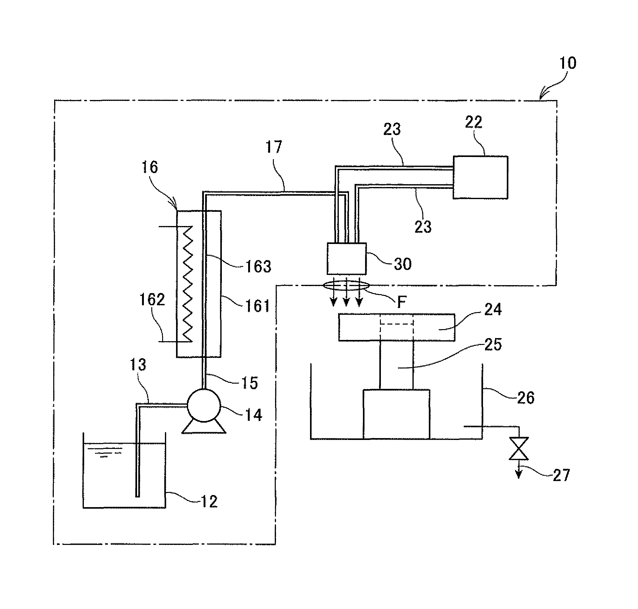
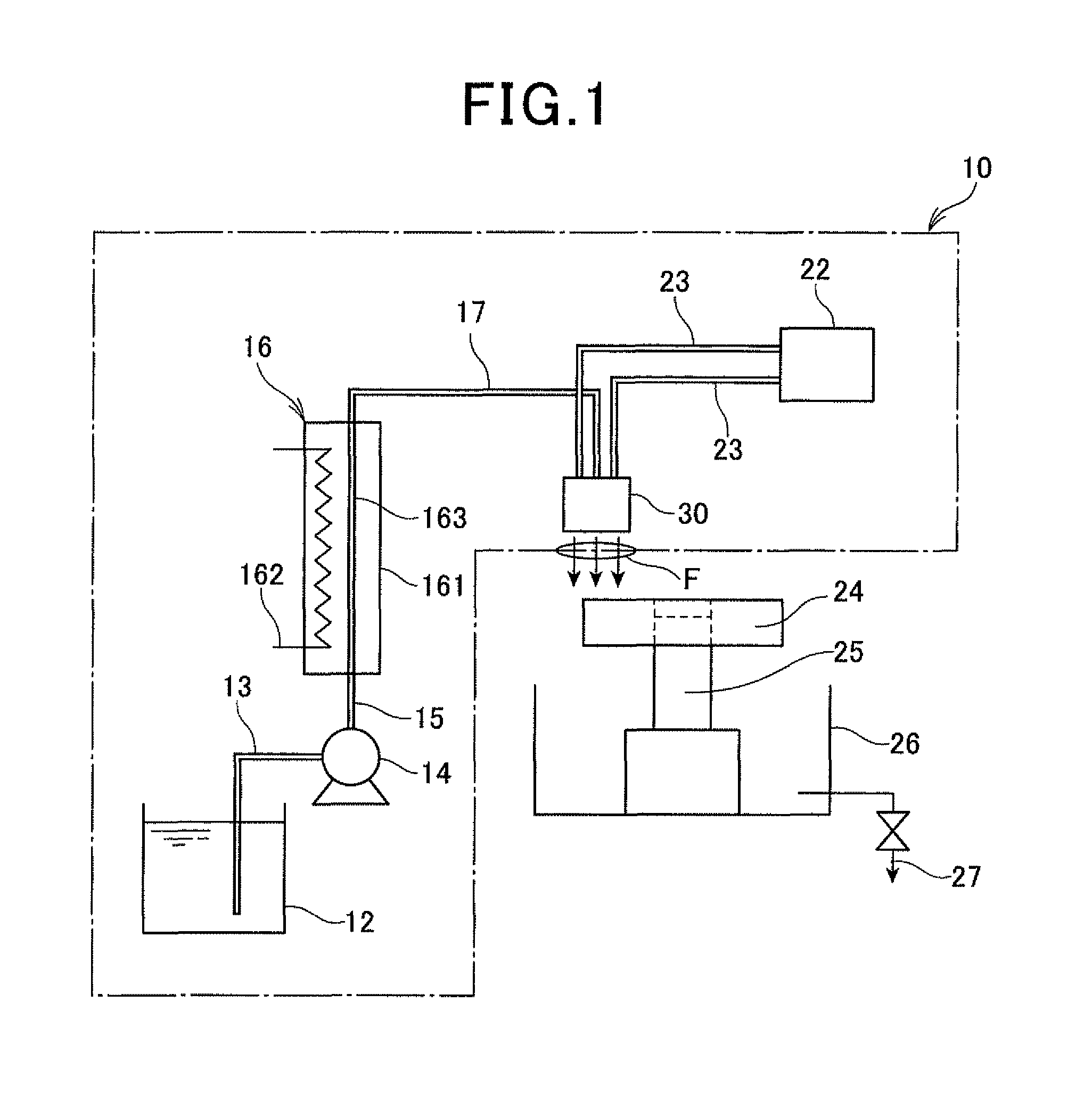
[0029]A cleaning apparatus 10 according to a first embodiment of the invention is described with reference to FIGS. 1 and 2. The cleaning apparatus 10 includes a reservoir tank 12, a booster pump 14 as a pressure-feed unit, a heat exchanger 16 as a heating unit, a compressor 22 as a gas supply unit and a nozzle block 30 as an injection unit. The cleaning apparatus 10 is for removing contamination from a vehicle component, which has adhered during a pre-process such as a machining process, in order to ensure the reliability and quality of the vehicle component necessary for a post-process. In FIG. 1, the arrows F indicate the direction in which a cleaning fluid and a gas injected from the nozzle block 30 flow.

[0030]The reservoir tank 12 is for reserving the cleaning fluid. The cleaning fluid used in the cleaning apparatus 10 may be water or water-containing alcohol with an added antirust agent. Preferably, the water-containing alcohol is an alcohol having a boiling point higher than ...

second embodiment

[0046]Next, a cleaning apparatus according to a second embodiment of the invention is described with reference to FIG. 3. The second embodiment differs from the first embodiment in the shape of the nozzle block.

[0047]FIG. 3A is a cross-sectional view of a nozzle block 40 of the cleaning apparatus according to the second embodiment of the invention. FIG. 3B is a bottom view of the nozzle block 40. The nozzle block 40 is formed with one fluid passage 42 and one gas passage 44 having an annular cross section. As shown in FIG. 3B, the gas passage 44 is provided with an annular gas injection hole 442 along a virtual circle Q2 whose center is the same as a center C2 of a fluid injection hole 422 of the fluid passage 42. The gas injection hole 442 is formed such that the distance L2 between the point 443 closest of all the points on its circular outer edge to the fluid injection hole 422 and the center C2 of the fluid injection hole 422 is 10 mm. The open area of the gas injection hole 442...

third embodiment

[0048]Next, a cleaning apparatus according to a third embodiment of the invention is described with reference to FIG. 4. The third embodiment differs from the second embodiment in the shape of the nozzle block.

[0049]FIG. 4A is a cross-sectional view of the nozzle block 50 of the cleaning apparatus according to the third embodiment of the invention. FIG. 4B is a bottom view of the nozzle block 50. The nozzle block 50 is formed with one fluid passage 52 and two gas passages 54 having an arcuate cross-section. As shown in FIG. 4B, each of the gas passages 54 is provided with a gas injection hole 542 having an arcuate shape along a virtual circle Q3 whose center is the same as a center C3 of a fluid injection hole 522 of the fluid passage 52. Each gas injection hole 542 is formed such that the distance L3 between the point 543 closest of all the points on its circular outer edge to the fluid injection hole 522 and the center C3 of the fluid injection hole 522 is 10 mm. The open areas of...


PUM


Abstract

The cleaning apparatus includes a reservoir tank for reserving a cleaning fluid, a pressure-feed unit for feeding the cleaning fluid while pressurizing the cleaning fluid above the atmospheric pressure, a heating unit for heating the cleaning fluid pressure-fed from the pressure-feed unit above an atmospheric pressure boiling point of the cleaning fluid, a gas supply unit for supplying a gas and an injection unit connected to the heating unit and the gas supply unit for injecting the cleaning fluid pressurized by the pressure-feeding unit and heated by the heating unit as a pressurized superheated cleaning fluid and the gas supplied from the gas supply unit to the member at the same time.

Description

[0001]This application claims priority to Japanese Patent Application No. 2012-195037 filed on Sep. 5, 2012, the entire contents of which are hereby incorporated by reference.BACKGROUND OF THE INVENTION[0002]1. Field of the Invention[0003]The present invention relates to a cleaning method and a cleaning apparatus used for performing the cleaning method.[0004]2. Description of Related Art[0005]Generally, to remove contamination or foreign matter from a member (a machined part or component, for example) which has adhered to the member during a manufacturing process of the member, or to remove remaining chemical liquid from the member which has been applied to the surface of the member during a surface treatment process of the member, a cleaning apparatus is used for injecting water or cleaning fluid to the member. Japanese Patent Application Laid-open No. 2005-296874 describes such a cleaning apparatus of the two-fluid nozzle type, which has a fluid injection nozzle for injecting flui...

Claims


Application Information

Patent Timeline
Patent Type & Authority Patents(United States)
IPC IPC(8): B08B3/00B08B7/00B08B3/02B08B5/02
CPCB08B7/0021B08B3/02B08B5/02B08B2203/007
Inventor OZEKI, YASUHITOYANAGAWA, KEITA
Owner DENSO CORP
Why Eureka
Try Eureka