
Elevator installation and a method for controlling elevators

a technology for elevators and installation methods, applied in elevators, transportation and packaging, etc., can solve the problem of only approximation of elevator energy consumption, and reduce the dimensioning of the reserve power device needed, increase the transport capacity of the elevator installation being supplied with the reserve power device, and smooth the effect of power variation

Active Publication Date: 2017-01-03
KONE CORP
View PDF13 Cites 5 Cited by
  • Summary
  • Abstract
  • Description
  • Claims
  • Application Information

AI Technical Summary

Benefits of technology

The patent describes a solution for reducing power variation in a building caused by elevators and other electrical devices. This is achieved by controlling the elevators and devices in the building using a central control system. The control system forms a plan for driving the elevators based on service requests, and the elevators are driven according to this plan by supplying electric power to the hoisting machines and receiving power back from the braking hoisting machines. This reduces the power variation in the electricity supply of the building and allows the elevators to continue operating without causing overload. The solution can also reduce the electricity consumption of the building by optimizing the power consumption of the hoisting machines and external devices. Overall, the solution improves the efficiency of the elevators and reduces the investment costs for the electricity supply of the building.

Problems solved by technology

Although the energy consumption of elevators is, in fact, only approx.

Method used


Image

  • Elevator installation and a method for controlling elevators
  • Elevator installation and a method for controlling elevators
  • Elevator installation and a method for controlling elevators

Examples


embodiment 1

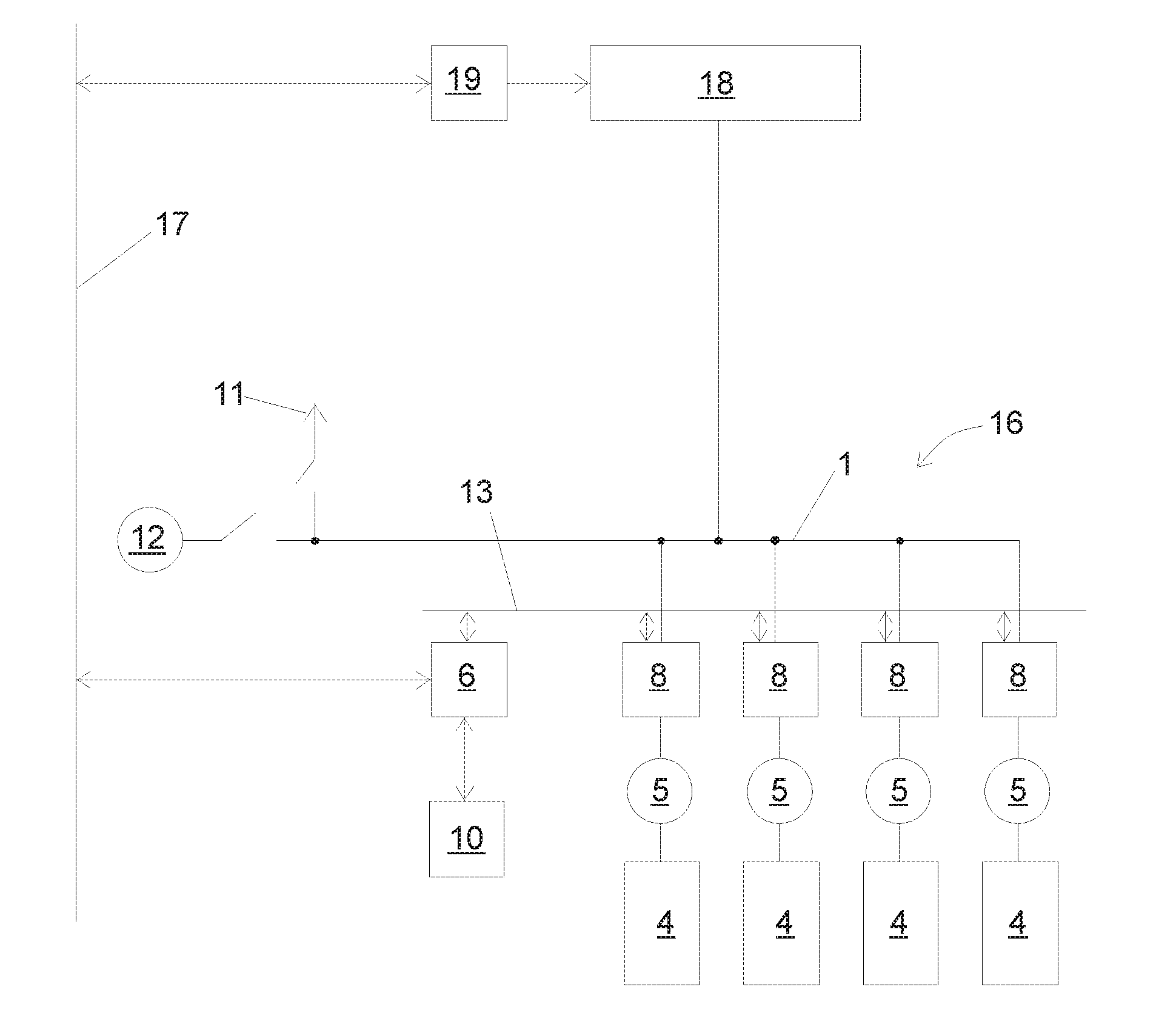
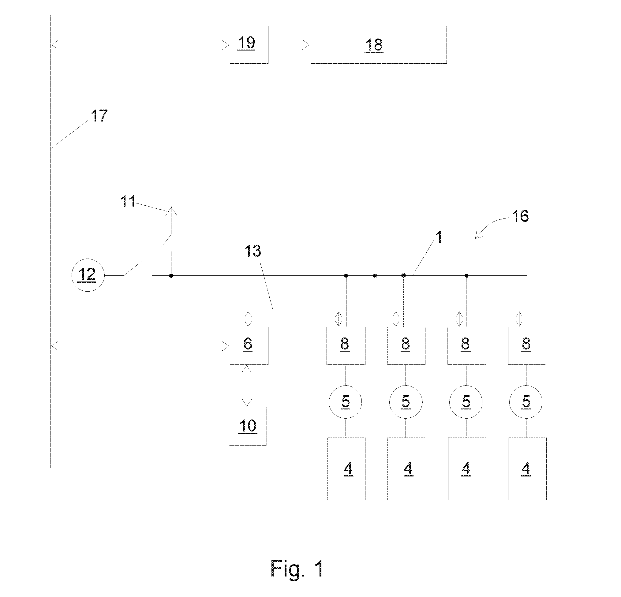
[0029]FIG. 1 presents an elevator installation in a building, which elevator installation comprises an elevator group 16. The group controller 6 receives service requests given by elevator passengers with call-giving devices 10, and allocates via the data transfer bus 13 the service requests received to be served by elevator cars 4 belonging to the elevator group 16. The group controller 6 forms a run plan, i.e. a plan about how service requests will be distributed in a coordinated manner between the elevator cars 4 of the elevator group 16.

[0030]The group controller 6 divides the service requests between the elevator cars, and each elevator car is driven on the basis of service requests in such a way that the elevator car stops at floors according to the service requests.

[0031]The elevator installation of FIG. 1 is connected to the three-phase electricity distribution network 1 of the building The electricity supply from the public electricity network to the electricity distributio...

embodiment 2

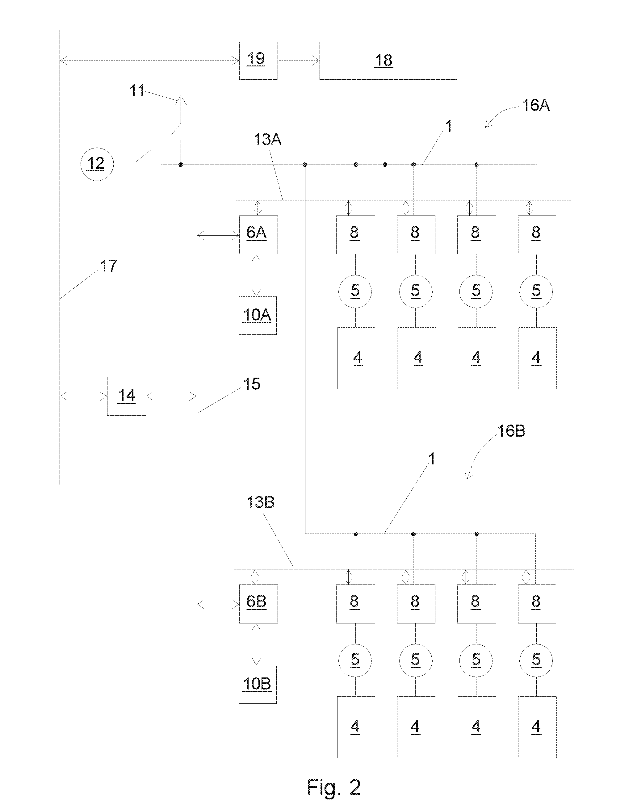
[0050]FIG. 2 presents an elevator installation in a building, in which, differing from FIG. 1, there are two elevator groups 16A and 16B, which have their own group controllers 6A and 6B. The group controller 6A receives service requests from the call-giving devices 10A and allocates via the data transfer bus 13A the service requests received to be served by elevator cars 4 belonging to the elevator group 16A. Correspondingly, the group controller 6B receives service requests from the call-giving devices 10B and allocates via the data transfer bus 13B the service requests received to be served by elevator cars belonging to the elevator group 16B. Both the group controllers 6A, 6B are configured to form a group-specific run plan in the same way, in terms of its basic principles, as is presented in the preceding embodiment 1.

[0051]The elevator installation of FIG. 2 also comprises a power management unit 14, which is connected with a data transfer bus 15 to the group controllers 6A, 6...

embodiment 3

[0057]FIG. 8 presents two buildings 25, 26, in both of which is an elevator installation according to embodiment 2 configured in such a way that in both buildings 25, 26 are two elevator groups 16A and 16B according to FIG. 2, each of which elevator groups has its own group controller 6A and 6B. In addition, in the building 25 is a power management unit 14 according to the embodiment of FIG. 2, which power management unit is connected to the building automation apparatus 19 of the building 25 as well as to the group controllers 6A, 6B. In addition, the power management unit 14 is connected by means of an internet connection 17 to the group controllers 6A, 6B that are in the second building 26 as well as to the building automation apparatus 19.

[0058]The electricity supply in the buildings 25, 26 to devices 18 that are external to the elevator installation are controlled with the building automation apparatuses 19.

[0059]The electricity supply 11 to both buildings 25, 26 occurs with th...


PUM


Abstract

The invention relates to an elevator installation and also to a method for controlling elevators. In the method a run plan is formed for driving elevator cars on the basis of service requests, the elevator cars are driven according to the run plan, by supplying electric power via the electricity distribution network of the building to a hoisting machine driving an elevator car, and also by supplying electric power from a hoisting machine braking an elevator car back to the electricity distribution network of the building, alternatives for a run plan are formed for driving elevator cars on the basis of service requests, the electric power which the hoisting machines need for implementing the aforementioned alternatives is determined, and also a run plan is selected for use from the plurality of different alternatives, when implementing which run plan the electric powers of the hoisting machines, when summed together, smooth the power variation occurring in the electricity supply of the building.

Description

[0001]This application is a continuation of PCT International Application No. PCT / FI2013 / 050856 which has an International filing date of Sep. 5, 2013, the entire contents of which are incorporated herein by reference.FIELD OF THE INVENTION[0002]The invention relates to the optimization of the power usage of elevators.BACKGROUND OF THE INVENTION[0003]The electrical energy requirement of elevators varies at different times. During a run the power requirement is essentially greater than during a standstill of the elevator. The load of the elevator car as well as, inter alia, the magnitude of the counterweight of the elevator car affect the power consumption during a run.[0004]The fuses of a rising main in a building as well as the cables are usually dimensioned according to a greater required power. Generally the costs of a mains electricity connection of a building increase when the dimensioning of the fuses / the power requirement of the building increases.[0005]From the viewpoint of ...

Claims


Application Information

Patent Timeline
Patent Type & Authority Patents(United States)
IPC IPC(8): B66B1/30B66B1/34
CPCB66B1/302B66B1/34
Inventor HANNINEN, ARITYNI, TAPIO
Owner KONE CORP
Learn More