Ventilation assisted passive cell freezing device

a cell freezing and passive technology, applied in the field of passive cell freezing devices, can solve the problems of imposing an even greater imbalance in the freezing rate between the exterior and interior vials of the cluster, the need for a circular array, and the need for samples to be transferred to archival storage, so as to maximize the exposure of the sample vial, maximize the contact, and maximize the effect of surface conta

Active Publication Date: 2017-01-03
COOL LAB LLC
View PDF20 Cites 7 Cited by
  • Summary
  • Abstract
  • Description
  • Claims
  • Application Information

AI Technical Summary

Benefits of technology

[0011]In some embodiments, the sample vial rack comprises a plurality of wells or openings for the purpose of receiving one or more sample vial tubes. In other embodiments, the rack forms an airtight seal with the rim such that gas must pass through the gas vents of the removable rack to move between the upper and lower chambers. For example, the removable rack in some embodiments comprises a continuous surface having a size and shape compatible interface with the rim protrusion around the perimeter of the chamber. The wells or opening are configured in some embodiments to maximize or minimize contact with the sample vial. For example, in some embodiments the removable rack comprises a thermoconductive material, such that the temperature of the vial sample is in part regulated by the temperature of the removable rack. In these embodiments, one can maximize surface contact between the vial sample and the opening or well of the rack. In other instances, the removable rack comprises a thermally inert material, such that the temperature of the vial sample is regulated primarily by contact with the gas within the insulating chamber. Accordingly, in these latter embodiments, one can limit contact between the removable rack and the sample vial, and so maximize exposure of the vial sample to the gas within the insulating chamber. The rack may further comprise one or more holes positioned between selected vials for the purpose of directing gas flow around the sample vials, or directly into contact with the sample vials. In various embodiments, the rack is composed of polypropylene or polyethylene or plastic blends of those two polymers as the main or only components.
[0012]In some embodiments, the sample rack and sample vial payload may be transferred as a single unit to an archival storage site, such as a sample freezer. As such, some systems of the present invention eliminate the need to transfer sample vials to an archival storage site individually.
[0013]In some embodiments, the sample vials are introduced into the removable rack after the removable rack is seated within the insulating chamber on the rim protrusion. In other instances, the sample vials are first loaded into the removable rack and then introduced into the insulating chamber by placing the removable rack into the insulating chamber. The insulating chamber includes a base and lid or cover, wherein upon placing the cover over the base (in some embodiments, the cover and base are configured to interlock when closed), the removable rack is enclosed within the insulating chamber, which then can be placed into an environment of reduced temperature. As the environmental gases in the reduced temperature environment will be of greater density than the warmer gases contained within the interior of the insulating chamber, colder gases will enter through the underside vent and displace the gases of greater temperature and lesser density which will in turn exit through the top vent. As the cold gases contact the warmer sample vials, thermal energy will be transferred to the gases from the vials. Upon gaining thermal energy, the gases will be reduced in density and become displaced by a continuous influx of colder gas. As such, by selective placement of gas passage holes in the rack surface, thermal energy may be removed from specific vials in the central portion of the vial cluster, thereby equalizing the rate of thermal energy loss from all vials contained within the chamber of the invention. The overall rate of thermal energy loss, and therefore the rate of sample vial temperature reduction, can be adjusted by various combinations of vent restriction, rack gas passage hole size and placement, and chamber insulation thickness.

Problems solved by technology

The need for a circular array places a practical limit on the number of vials that can be contained in a freezing unit, as the circumference of the device increases in a linear proportion to the number of vials contained therein.
To maintain the desired temperature reduction profile, a greater quantity of thermal energy will need to be released per unit time, thereby necessitating a reduction in the thickness of the insulation of the passive cooling device, thereby imposing an even greater imbalance in the freezing rates between the exterior and interior vials of the cluster.
As the sample capacity of the freezing device is increased, a secondary problem arises in that, upon completion of the freezing process, the samples will need to be transferred to archival storage.
Transferring the vials individually is both time consuming and presents opportunity for frozen specimens to warm, thereby presenting a great threat to the integrity and viability of the frozen cells.

Method used


Image

  • Ventilation assisted passive cell freezing device
  • Ventilation assisted passive cell freezing device
  • Ventilation assisted passive cell freezing device

Examples


Embodiment Construction

[0021]The present invention will be described with regard to the accompanying drawings, which assist in illustrating various features of the invention.

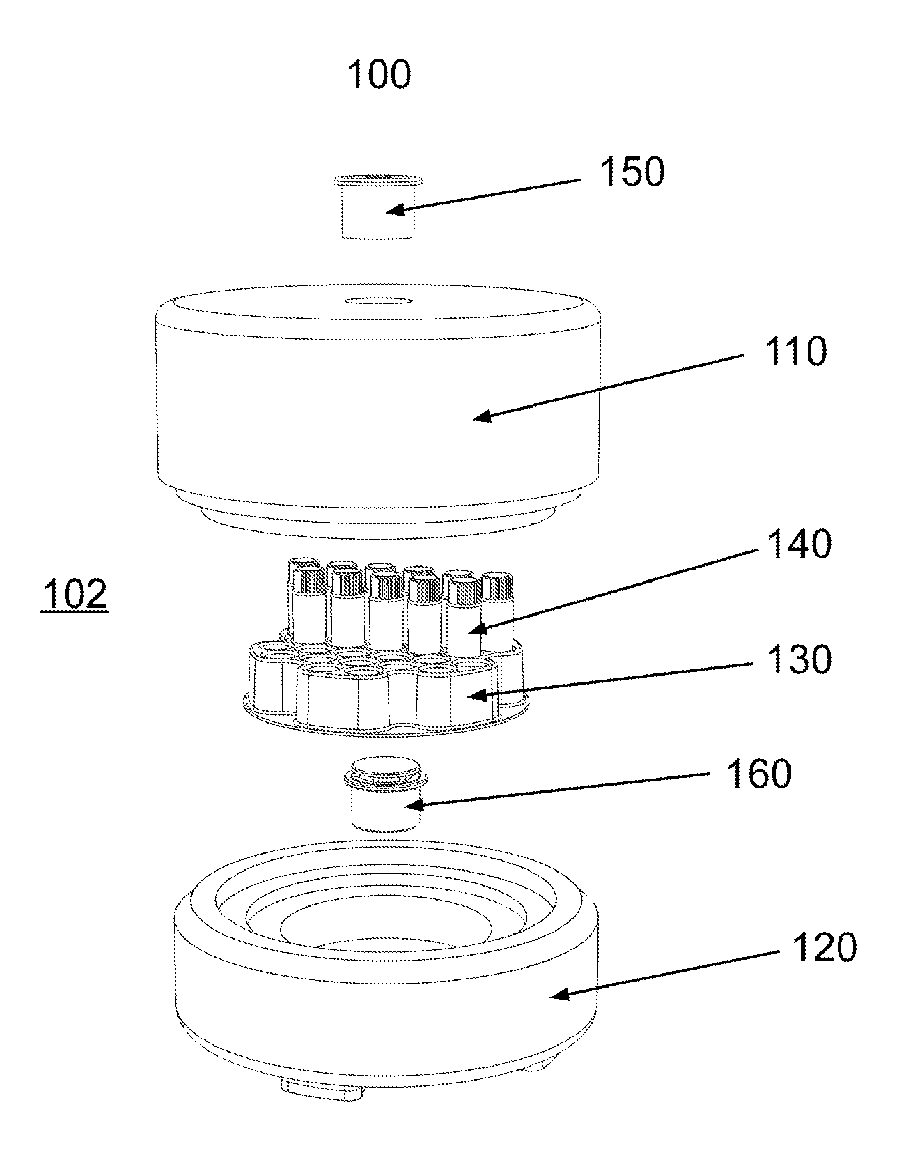
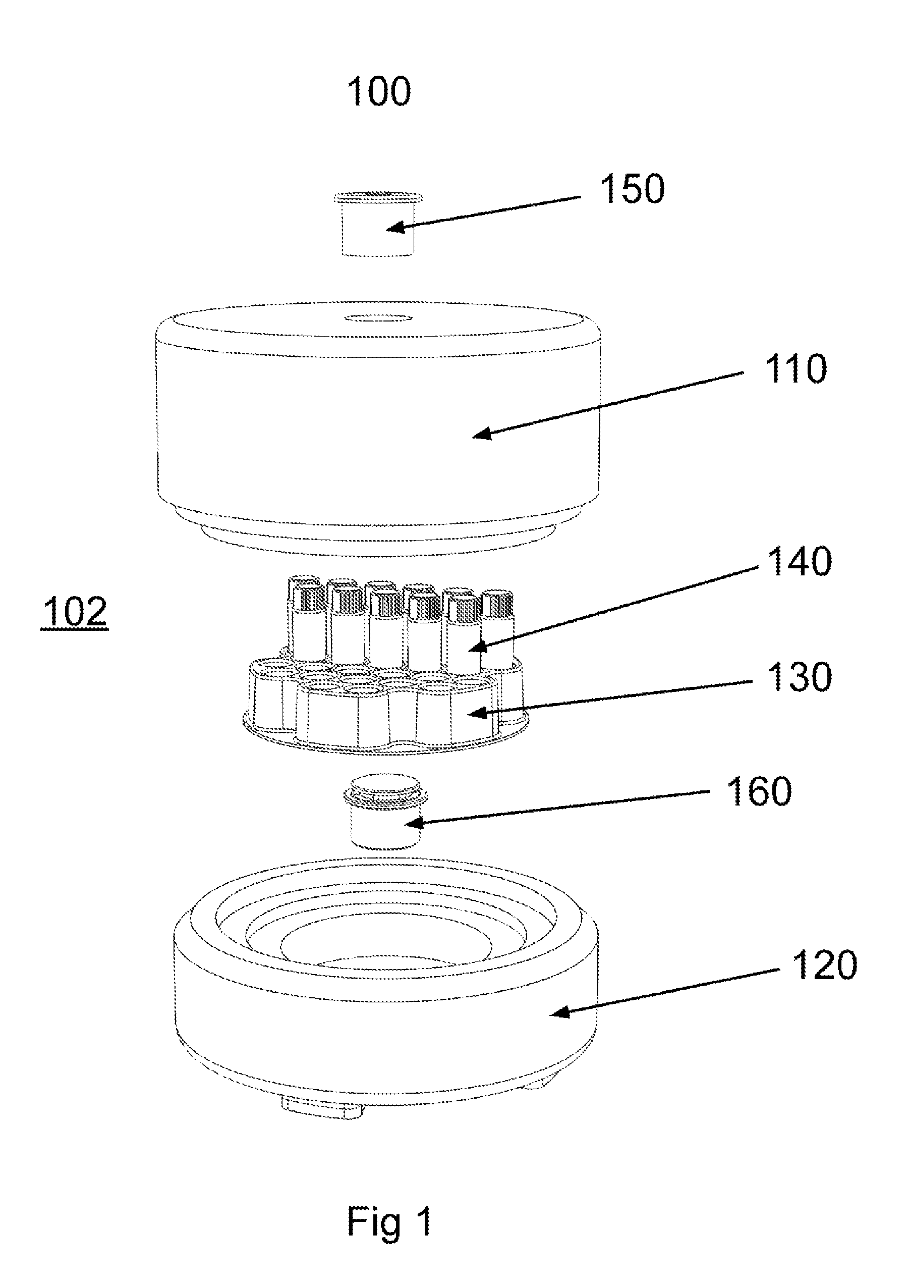
[0022]Referring now to FIG. 1, a sample freezing apparatus 100 is shown. Sample freezing apparatus 100 generally comprises an enclosure having an internal, insulating chamber in which a removable rack 130 is placed and enclosed. The insulating chamber of sample freezing apparatus 100 generally comprises a thermo-insulating material, such as polyethylene, polystyrene, or polyurethane foam materials. The insulating chamber may further include additional materials to enhance or otherwise optimize the insulating needs of the device. For example, apparatus 100 may comprise additional internal or external insulating material to provide additional insulation. Alternatively, apparatus 100 may comprise one or more compartments or lines for the addition of a cooling agent, such as liquid nitrogen or a pre-cooled ballast mass.

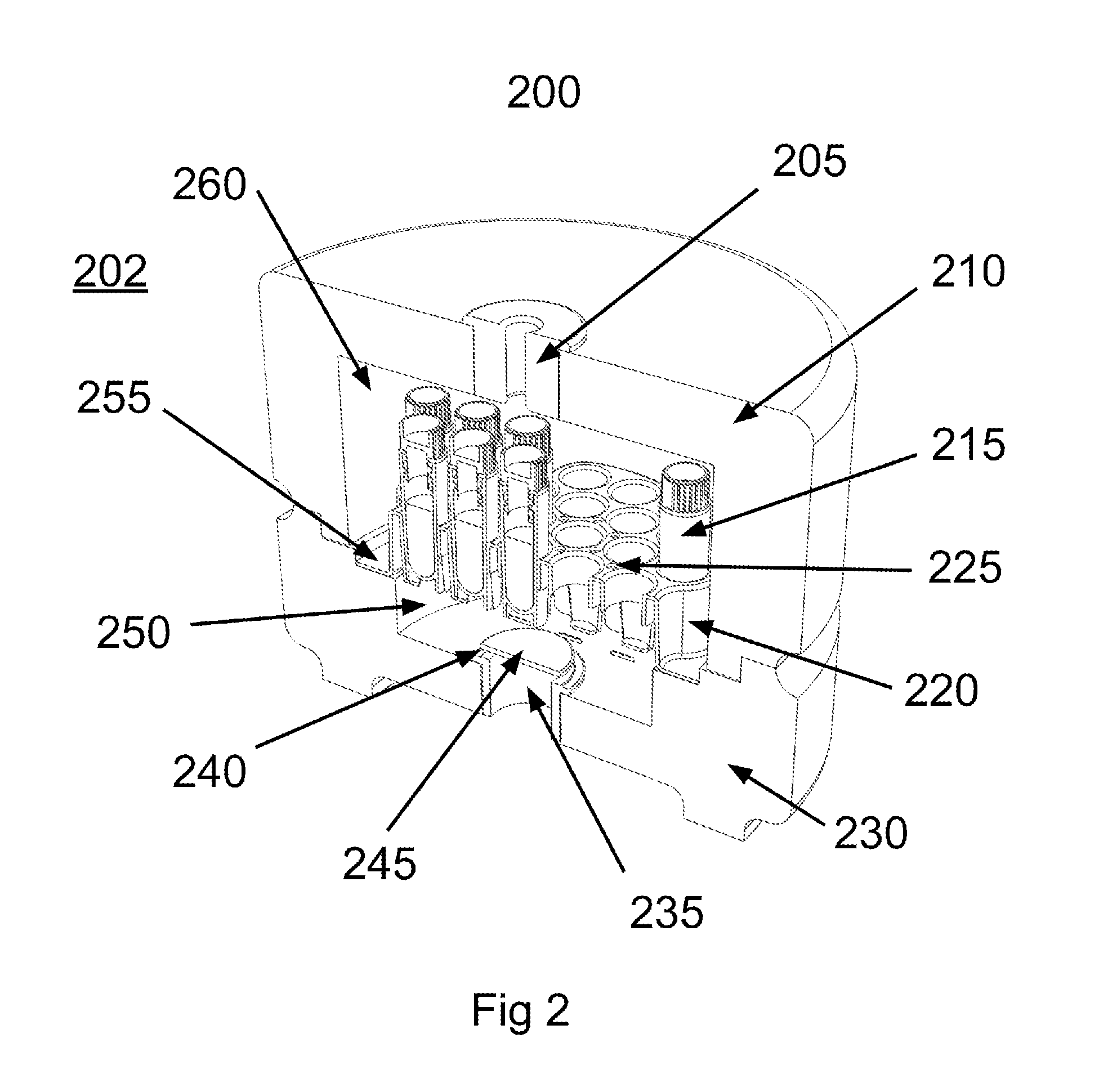
[0023]In some embod...


PUM

PropertyMeasurementUnit
heightaaaaaaaaaa
heightaaaaaaaaaa
thicknessaaaaaaaaaa

Abstract

A system and method for concurrently and uniformly removing thermal energy from clustered specimen samples.

Description

[0001]This application is a National Stage of International Application No. PCT / US2012 / 038431, filed May 17, 2012, and entitled VENTILATION ASSISTED PASSIVE CELL FREEZING DEVICE, which claims the benefit of U.S. Provisional Application No. 61 / 487,445, filed May 18, 2011, and entitled VENTILATION ASSISTED PASSIVE CELL FREEZING DEVICE. This application claims priority to and incorporates herein by reference the above-referenced applications in their entirety.BACKGROUND OF THE INVENTION[0002]Maximizing the percentage of suspended cells recovered live following freezing, archival storage, and thawing requires that a specific temperature reduction profile be applied (see U.S. Patent Application Pub. No. 2011 / 0308271 and PCT Pub. No. 2011 / 159934, each of which is incorporated herein by reference). When freezing multiple vials concurrently, it is therefore critical that each vial experience the same desired profile. While passive cell freezing systems offer a significant cost savings over ...

Claims


Application Information

Patent Timeline
Patent Type & Authority Patents(United States)
IPC IPC(8): G01N1/42A01N1/02
CPCG01N1/42A01N1/0252
Inventor SCHRYVER, BRIANGANAJA, SCOTT
Owner COOL LAB LLC
Why Eureka
Try Eureka