Drive unit for a motor vehicle and cooling device for a motor vehicle

A technology of cooling device and drive unit, applied in engine cooling, machine/engine, transmission parts, etc., can solve the problems of high cost, parts susceptible to failure, etc., and achieve low cost, low weight, and increased heat transfer Effect

Active Publication Date: 2022-04-15
FORD GLOBAL TECH LLC
View PDF7 Cites 0 Cited by
  • Summary
  • Abstract
  • Description
  • Claims
  • Application Information

AI Technical Summary

Problems solved by technology

Components are also susceptible to failure and can be costly

Method used


Image

  • Drive unit for a motor vehicle and cooling device for a motor vehicle
  • Drive unit for a motor vehicle and cooling device for a motor vehicle

Examples


Embodiment Construction

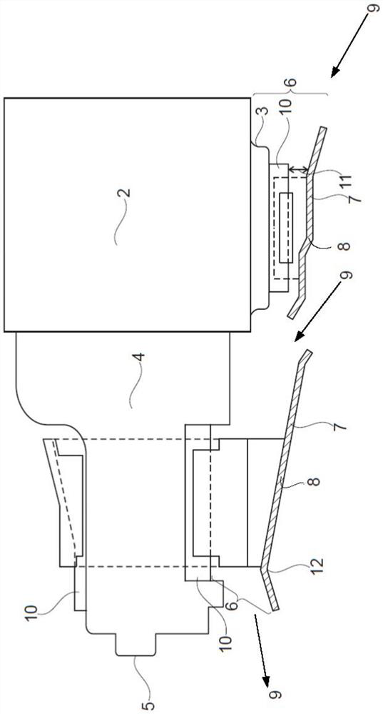
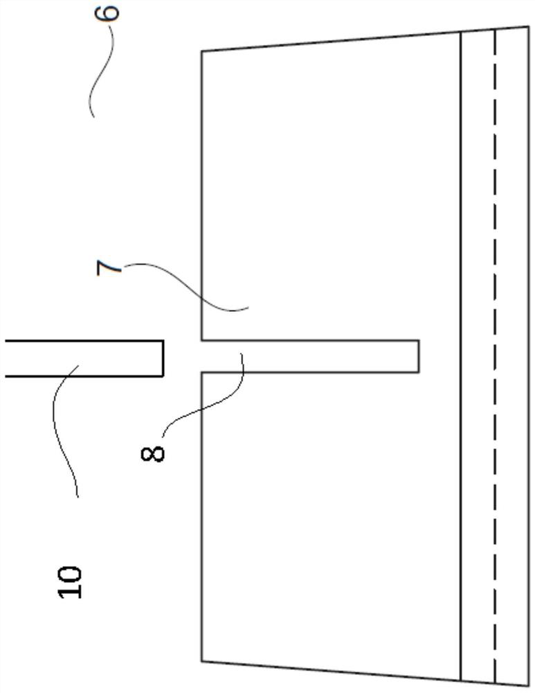
[0016] The following description relates to systems and methods and systems for a cooling device for a vehicle. These cooling devices can improve a vehicle's cooling performance by directing cooling fluid through the vehicle's critical components. For example, a cooling unit can direct air through the motor oil pan, which reduces heat from the motor oil. In addition, the cooling device can further conduct heat from vehicle components. For example, the sheet metal cooling device can be connected to the transmission housing via metal fastening devices. In this embodiment heat is transferred from the transmission housing via the fastening device to the cooling device.

[0017] One embodiment includes a drive unit for a motor vehicle having: a motor with a motor sump for supplying motor oil; a transmission with a transmission housing for supplying transmission oil; Cooling device for motor oil and / or transmission oil temperature. The cooling device may extend along the motor o...


PUM


Abstract

The present application provides methods and systems for cooling devices connected to components of a motor vehicle. The cooling device affects the flow of fluid moving through the vehicle components. In one example, the system may include a cooling device positioned below the oil sump. The cooling arrangement may feature equipment such that fluid flows between the equipment and the oil pan. The cooling device can also be positioned under the transmission housing.

Description

[0001] Cross References to Related Applications [0002] This application claims priority from German Application No. 102017202789.4 filed on February 21, 2017. The entire contents of the applications cited above are hereby incorporated by reference in their entirety for all purposes. technical field [0003] The present description generally relates to methods and systems for installing cooling devices to vehicle components. Background technique [0004] The present application relates to a drive unit for a motor vehicle comprising a motor with a motor oil sump and a transmission. The transmission may include a transmission housing. Cooling devices may be used to reduce the temperature of the motor, transmission, or both. [0005] Cooling of the motor oil or transmission oil is often utilized even during normal operation. Cooling can further be utilized at high payloads, trailer loads or high motor rotational speeds. [0006] Previous attempts at cooling transmission o...

Claims


Application Information

Patent Timeline
Patent Type & Authority Patents(China)
IPC IPC(8): F01P9/04F16H57/04B62D35/02
CPCB62D35/02F01P9/04F16H57/0412F01M5/002F01M2011/0025F01M11/0004F01M2011/0058F16H57/0423B60K11/06
Inventor B·格拉卡
Owner FORD GLOBAL TECH LLC
Why Eureka
Try Eureka