Cryogenic device for surgical use

a cryogenic device and surgical technology, applied in the field of cryogenic devices for medical applications, can solve the problems of increasing manufacturing costs, increasing complexity, and increasing complexity of devices of the prior art, and achieves the effects of reducing manufacturing costs globally, improving efficiency, and facilitating the operation of surgical instruments

Active Publication Date: 2017-01-10
PAQUES BV NL
View PDF28 Cites 0 Cited by
  • Summary
  • Abstract
  • Description
  • Claims
  • Application Information

AI Technical Summary

Benefits of technology

[0005]In order to remedy such drawbacks, the invention aims at providing a cryogenic device to be used once which can be reliable and the manufacturing of which is simple and less expensive. Another object of the invention is also to provide a light ergonomic, sterile and secured cryogenic device.
[0006]For this purpose and according to a first aspect, the invention provides a cryogenic device for surgical use making it possible to cool an area of the body including:
[0010]Advantageously, the end piece is made integral with one end of the flexible tube using gluing means. Then, the number of parts is limited by the utilisation of glue and the mounting is particularly simple. Of course using glue is possible only if the probe is sterilised at a low temperature. In practice, low temperature sterilisation, for example using 45° ethylene oxide, requires extractors which are not available in hospitals and it is thus mainly performed under industrial conditions. As a matter of fact, an attachment using a simple gluing step can be considered only because the mounting of the device is much simplified by the utilisation of a two-conduit unique tube; and thus the manufacturing cost can be globally reduced so much so that a one-time use is economically justified.

Problems solved by technology

Manufacturing the devices of the prior art is expensive, takes time and is difficult more particularly because of the number of parts which compose the same.
Because the French standard is still more restricting since it requires a 20 minutes' stay at 134° C. Such constraints imply technological choices which make the devices still more complex and more expensive.
In addition, sterilised devices using this procedure undergo deteriorations imposing frequent and costly maintenance actions when and as they are sterilised.
Then, the number of parts composing the device is limited.

Method used


Image

  • Cryogenic device for surgical use
  • Cryogenic device for surgical use
  • Cryogenic device for surgical use

Examples


Embodiment Construction

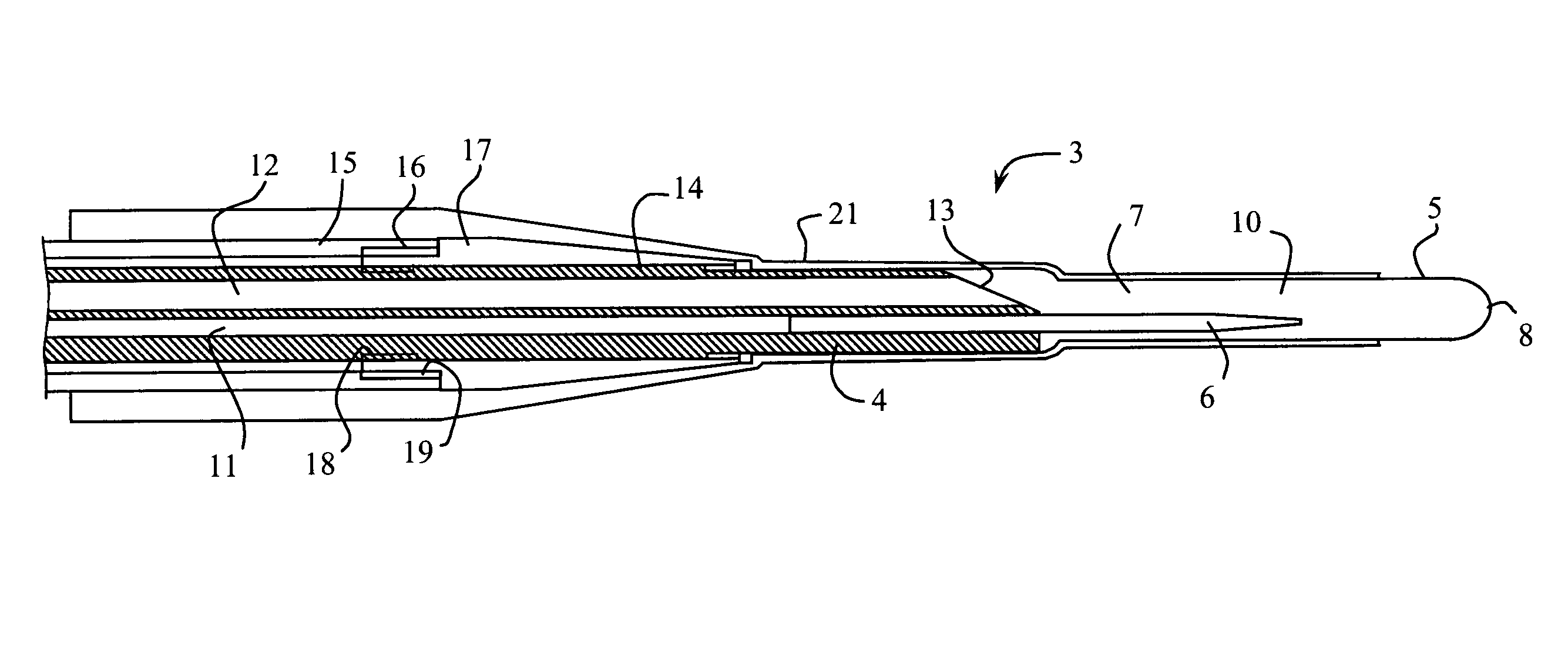
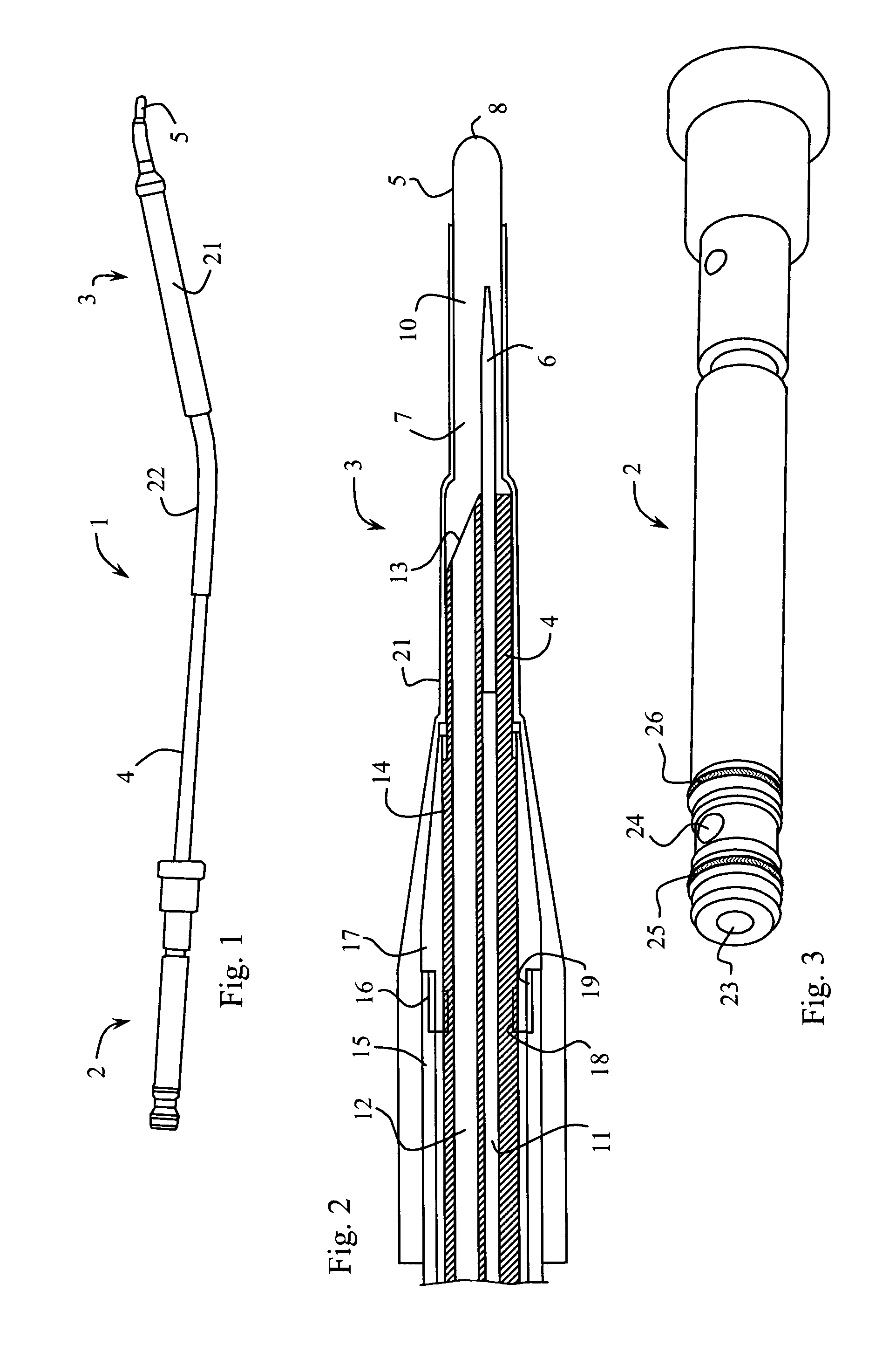
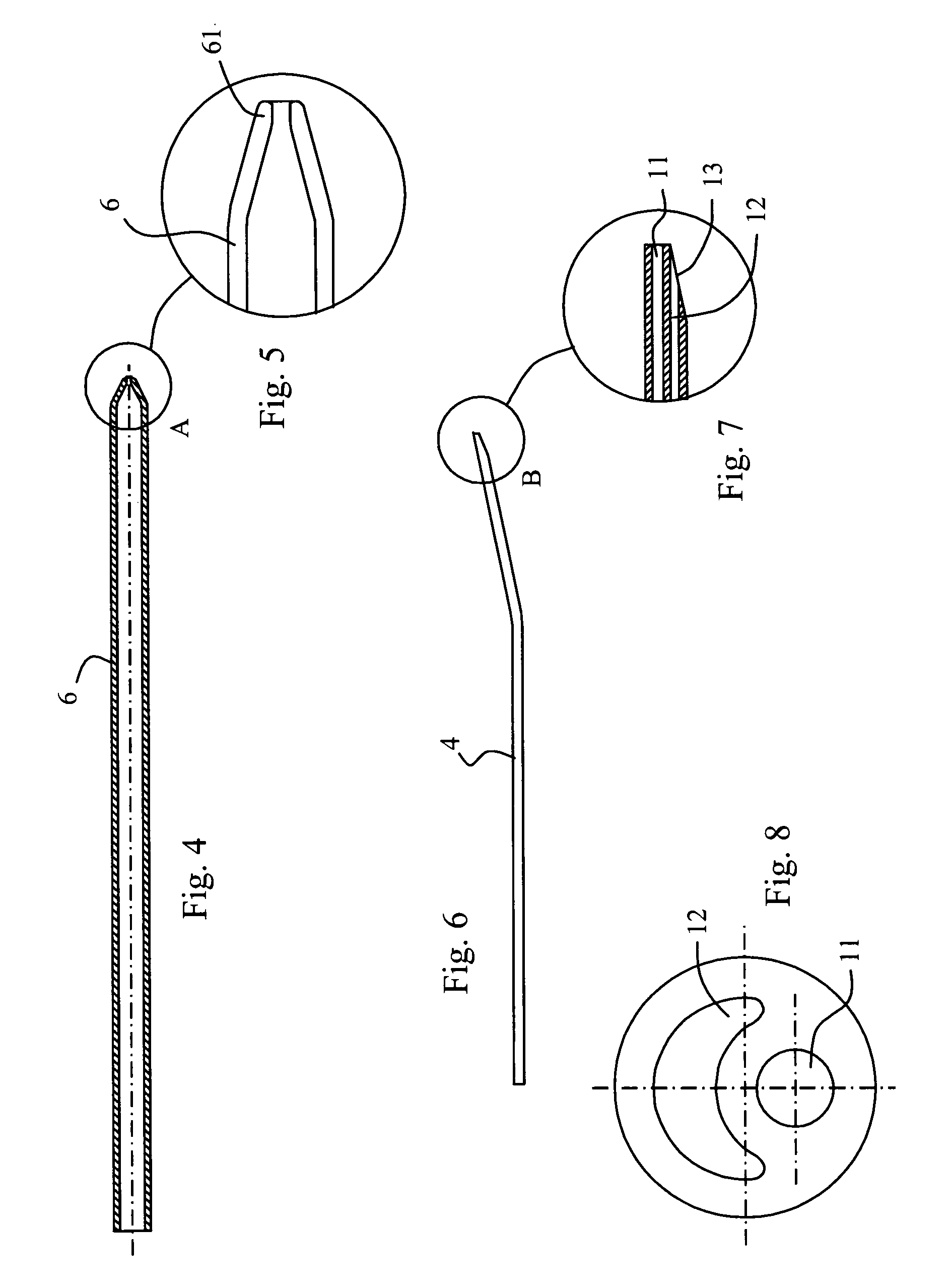
[0026]FIG. 1 shows a cryogenic device 1 according to the invention including a connector 2 intended to be coupled to a liquefied gas tank release valve (nitrous oxide or carbon dioxide) on the one hand, a probe or cryoextractor 3 on the other hand and a flexible tube 4 for transporting the cryogenic fluid connecting the connector 2 to the cryoextractor 3. The cryoextractor 3 shown in FIG. 2 includes a hollow end piece 5, the end of which is intended to be brought into contact with the area to be cooled and an injection nozzle 6 opening into the chamber 7 of the end piece 5 and spraying the cryogenic gas against the end 8 of the cryoextractor 3. Thus, the cryogenic gas cools the walls of the end piece 5 at the end 8 which will be applied onto the tissues to freeze them locally at a temperature lower than −50° C. and preferably of the order of −65° C. to −90° C.

[0027]The end piece 5 shown in FIG. 9 is made of a metallic material such as stainless steel, and the walls thereof form a ga...


PUM


Abstract

The disclosure relates to a cryogenic device for surgical use, which can be used to cool an area of the body and includes: a cryogenic gas supply conduit and a discharge conduit, an end piece comprising a metal tip intended to be brought into contact with the area to be cooled and a gas release chamber and a gas injection nozzle connected to the supply conduit at the one end and opening into the chamber in the direction of the metal tip at the other end. The supply conduit and the discharge conduit are formed in a common flexible extruded tube that is inserted into the end piece.

Description

CROSS-REFERENCE TO RELATED APPLICATIONS[0001]This application is a National Phase Entry of International Application No. PCT / FR2008 / 000720, filed on May 27, 2008, which claims priority to French Application 0755370, filed on May 31, 2007, both of which are incorporated by reference herein.BACKGROUND AND SUMMARY[0002]The invention relates to a cryogenic device for medical applications. The invention more particularly relates to cryogenic device to be used once for ophthalmologic surgery.[0003]In the prior art, cryogenic devices for medical applications are known. Such devices are more particularly used in the field of ophthalmologic cryosurgery and more particularly to treat retinal detachment by generating a cold point making it possible to create an adhesive scar by burning tissues between the retina and the choroid. The devices of the prior art are generally composed of a supply conduit connected to a source of cryogenic gas (nitrous oxide, carbon dioxide), of a conduit for discha...

Claims


Application Information

Patent Timeline
Patent Type & Authority Patents(United States)
IPC IPC(8): A61B18/02A61B18/00
CPCA61B18/02A61B2018/00023A61B2018/0262
Inventor AUMAITRE, OLIVIER
Owner PAQUES BV NL
Why Eureka
Try Eureka