Main frame for mobile bulk processing apparatus

a technology of mobile bulk material and main frame, which is applied in the direction of chemistry apparatus and processes, solid separation, grain treatment, etc., can solve the problems of common damage to the conveyor of conventional plants during transportation, and achieve the effect of convenient and quick adaptability

Active Publication Date: 2017-01-10
SANDVIK INTELLECTUAL PROPERTY AB
View PDF15 Cites 2 Cited by
  • Summary
  • Abstract
  • Description
  • Claims
  • Application Information

AI Technical Summary

Benefits of technology

[0007]It is an objective of the present invention to provide a mobile bulk material processing plant, such as a mobile crusher or screener that is conveniently and quickly adaptable between an operative and a transport position to allow the plant to be transported between sites. It is a further specific objective to protect, as far as possible, selected operative components of the plant during transportation.
[0008]The objectives are achieved via a processing plant that comprises a main frame, at least a part of which comprises a pair of opposed beams or frame members that are spaced apart in a widthwise direction across the plant to accommodate at least part or all of a conveyor operative to transport material to or from the plant. The conveyor is mounted at the main frame via one or a plurality of couplings that manipulate and change the relative configuration of the conveyor between the operative and transport positions. Preferably, the plant comprises a primary pivot joint to allow the conveyor to slew laterally relative to the main frame. Preferably, the plant further comprises a plurality of additional pivot mountings that allow the conveyor to be raised and lowered relative to the main frame and in particular to position at least part of the conveyor between the opposed beams. This transport configuration provides protection for the conveyor from undesirable damage due to objects on the road and structures (or objects) that project into the road.
[0014]Preferably, the apparatus further comprises at least one cross beam or brace extending between and linking the opposed beams in a widthwise direction of the apparatus. The cross beam is beneficial to stabilise the opposed frame beams and prevent undesirable twist or independent movement.
[0016]Preferably, the conveyor comprises a head and tail section pivotally mounted together to allow the head section to bend or fold relative to the tail section to raise and lower a distal end of the conveyor relative to the opposed beams. Preferably, the head section is positionable between the opposed means when the conveyor is raised to the transport position. A conveyor with a pivotally mounted head and tail section is advantageous to allow the distal end of the conveyor to be raised above the ground to a maximum height in an operative mode that in turn allows bulk stock piling of the processed material far away from the plant main frame and convenient adaptation to the transport position where the head section is installed between the opposed beams.
[0017]Preferably, the apparatus further comprises a plurality of power operated linear actuators to drive bending or folding of the head section relative to the tail section. Preferably, the apparatus comprises a first set of actuators operating and attached to the tail section and a further set of actuators operating and attached to the head section. This is advantageous to allow independent and / or combined raising and lowering movement of the head and tail sections.

Problems solved by technology

However, the conveyor of conventional plants is exposed during transportation and is commonly damaged by contact with objects that may be propelled upward from the road (such as tyre debris) or project into the road (such as trees or other encroaching structures like bridges, lights, signs and the like).

Method used


Image

  • Main frame for mobile bulk processing apparatus
  • Main frame for mobile bulk processing apparatus
  • Main frame for mobile bulk processing apparatus

Examples


Embodiment Construction

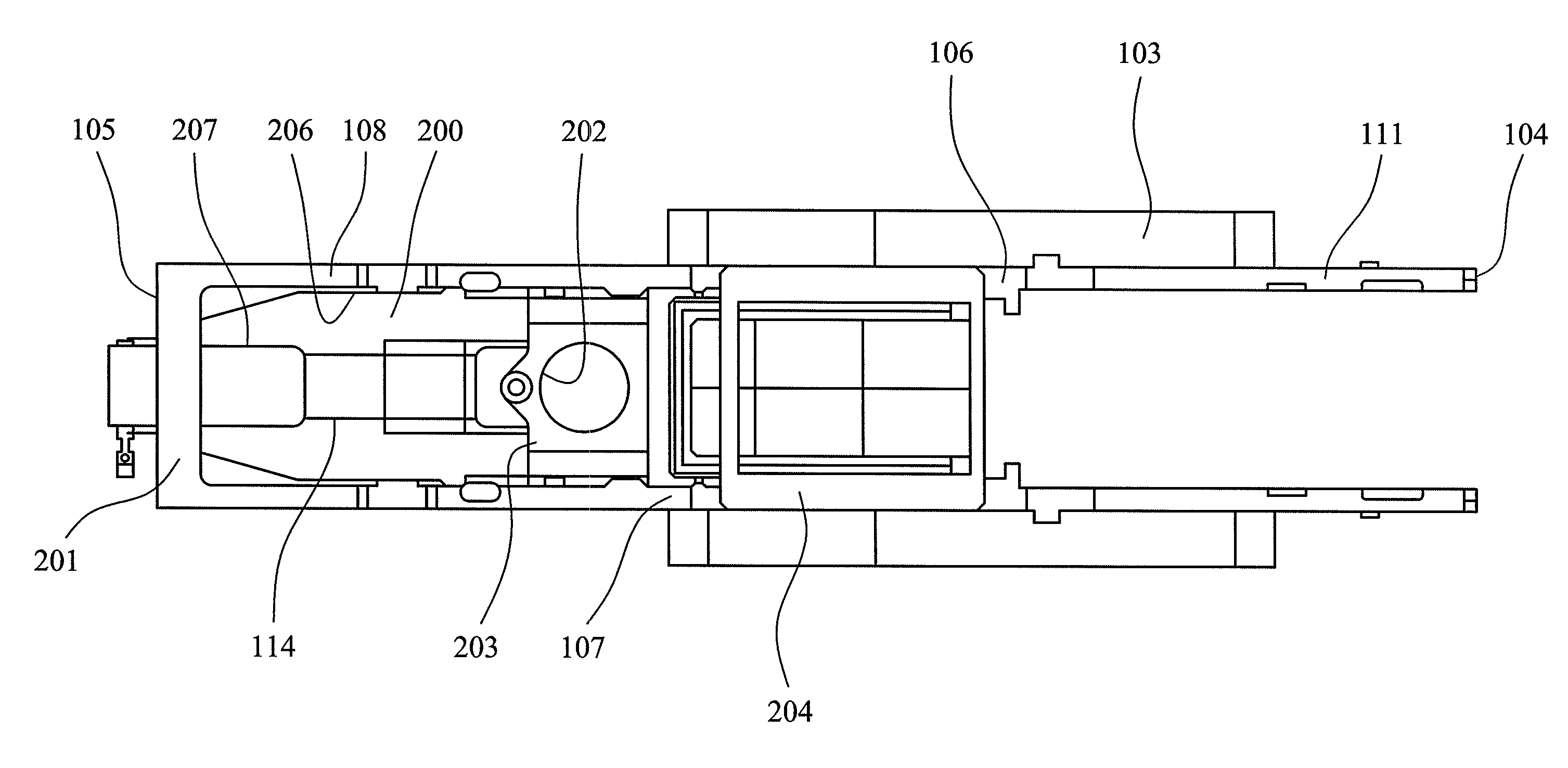
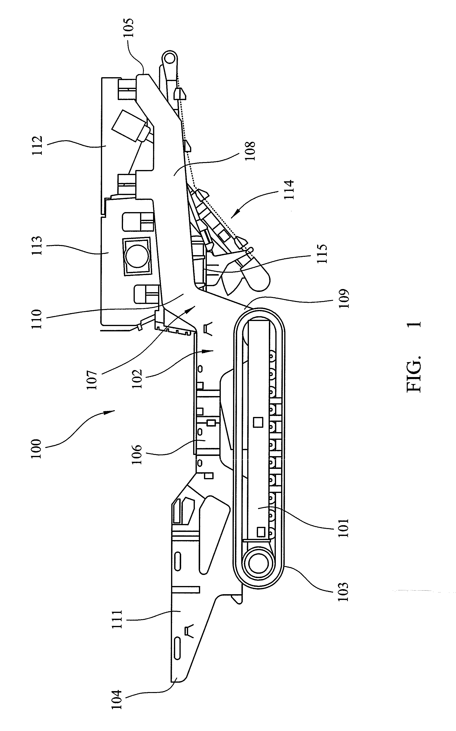
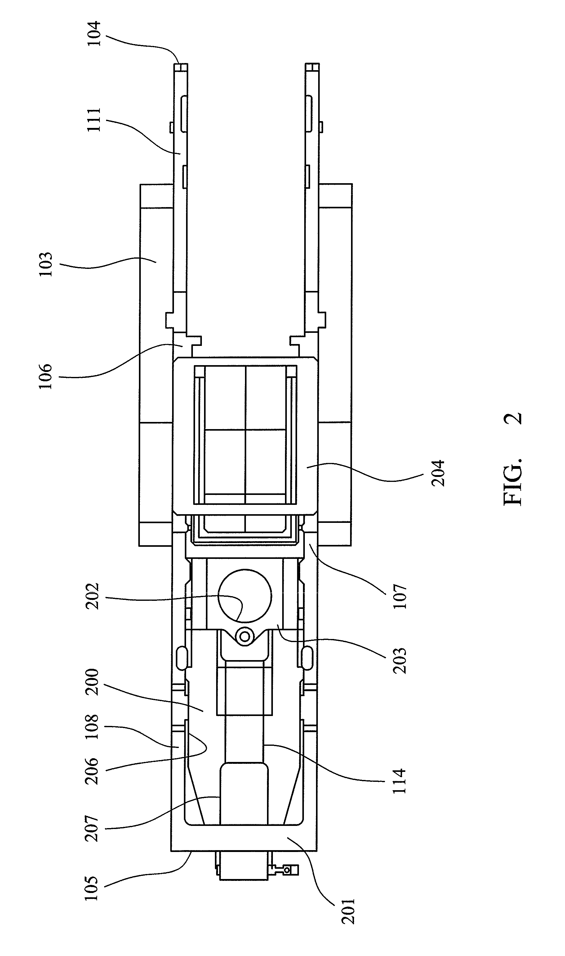
[0030]Referring to FIGS. 1 and 2, a mobile processing plant 100 comprises a main frame (or chassis) 102 that provides a central support for the various operative components of the plant 100. Frame 102 is movably mounted on the ground via an undercarriage 101 that carries a pair of opposed endless tracks 103 that are driven by a suitable power unit (not shown) to propel plant 100 over the ground. Frame 102 comprises a pair of parallel and longitudinally extending frame members that extend from a forward end 105 to a rearward end 104. Each frame member is spaced apart in a widthwise direction perpendicular to the main length between ends 105, 104. A central frame region 106 provides support for a mount 204 to mount the power unit and a primary plant processing unit (not shown). As will be appreciated, the processing unit may comprise a crusher such as a gyratory, impact, vibration or jaw crusher. Alternatively or in addition, the main processing unit may comprise a screening unit or a...


PUM


Abstract

A mobile bulk material processing apparatus includes a main frame having a pair of opposed beams that are spaced apart in a widthwise direction across the apparatus. A conveyor transports material from or to a material processing unit mounted at the main frame. The beams are arranged to receive at least part of the conveyor to protect the conveyor in a raised transport position.

Description

RELATED APPLICATION DATA[0001]This application is a §371 National Stage Application of PCT International Application No. PCT / EP2014 / 063530 filed Jun. 26, 2014 claiming priority of EP Application No. 13180383.5, filed Aug. 14, 2013.FIELD OF INVENTION[0002]The present invention relates to mobile bulk material processing apparatus and in particular, although not exclusively, to mobile apparatus in which a main frame comprises a pair of opposed beams spaced apart to accommodate at least part of a conveyor when the apparatus is adapted for transportation.BACKGROUND ART[0003]Mobile bulk material processing apparatus has been developed for a wide variety of applications including the processing of stone, minerals, construction materials and both domestic and industrial waste to generate smaller and / or size categorised aggregate for subsequent processing, use or disposal. For example, in both a quarry or clearance site environment, a mobile crusher is used to crush stone, rubble or site cle...

Claims


Application Information

Patent Timeline
Patent Type & Authority Patents(United States)
IPC IPC(8): B65G41/00B07B1/00B02C23/08B02C21/02
CPCB02C21/026B02C23/08B07B1/005B65G41/002B65G41/005Y02W30/58
Inventor MCDEVITT, TERRY
Owner SANDVIK INTELLECTUAL PROPERTY AB
Why Eureka
Try Eureka