Battery block
a battery block and block technology, applied in the field of battery blocks, can solve the problems of abnormal heat generation, chain reaction of degradation and abnormalities of the accommodated unit cells, and the characteristic degradation of the normal unit cell also undergoes abnormalities, so as to prevent the chain reaction of degradation and abnormalities of the unit cell
- Summary
- Abstract
- Description
- Claims
- Application Information
AI Technical Summary
Benefits of technology
Problems solved by technology
Method used
Image
Examples
embodiment 1
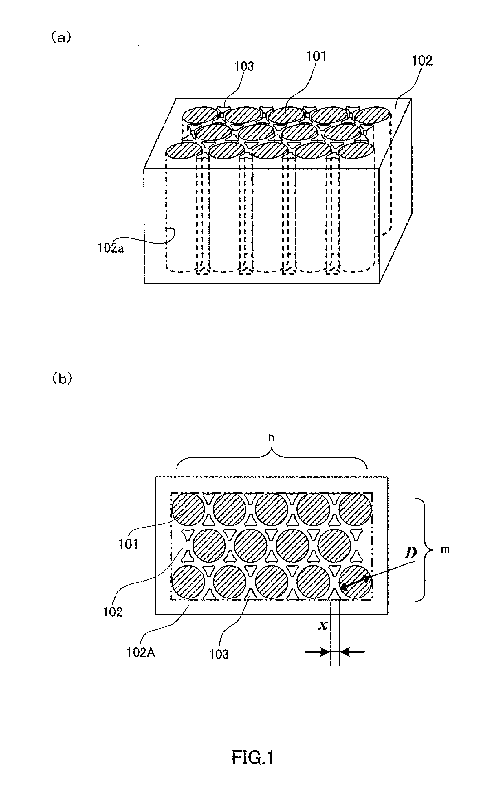
[0101]Referring to FIGS. 1 to 6, Embodiment 1 of the present invention will be described.
[0102]First, the configuration of a battery block of Embodiment 1 will be described with reference to FIG. 1. FIG. 1(a) is a perspective view schematically showing the battery block of Embodiment 1. FIG. 1(b) is a diagram viewed from above the battery block of FIG. 1(a).
[0103]In FIGS. 1(a) and 1(b), reference sign 101 denotes a cylindrical unit cell. Unit cell 101 has a cell capacity of A (Ah). Unit cell 101 has an outer diameter of D (m). Reference sign 102 denotes a battery case for accommodating therein unit cells 101. Battery case 102 includes peripheral portion 102A and a central portion surrounded by peripheral portion 102A. A plurality of circular holes 102a are arranged at the central portion. Hole 102a has a size such that unit cell 101 can be inserted in hole 102a without difficulty. A plurality of holes 102a are arranged in a staggered arrangement in order to increase the volumetric e...
embodiment 2
[0143]Embodiment 2 will now be described with reference to FIG. 7. FIG. 7 is an enlarged top view around abnormally heated unit cell 101A in the battery block of Embodiment 2.
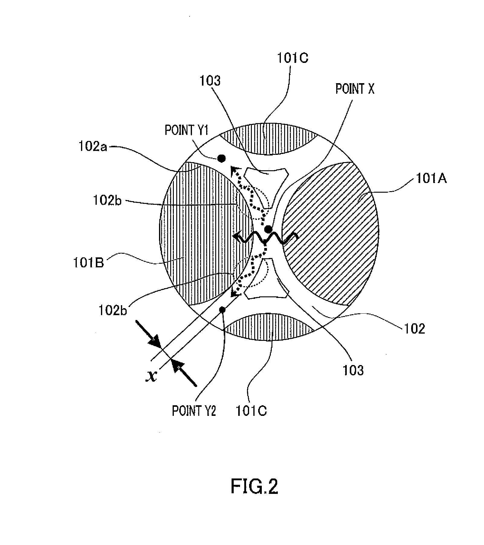
[0144]The battery block of this embodiment has a configuration analogous to that of Embodiment 1 except that the battery block of this embodiment does not have through hole 103. Thickness x of minimum thickness section 102b of battery case 102 in this embodiment is a thickness between unit cells 101B and 101C. Thickness x of minimum thickness section 102b in this embodiment is found using Equation 1 as with Embodiment 1.
[0145]Battery case 102 in this embodiment can be arranged such that the distances between the unit cells are reduced in comparison with the battery case in Embodiment 1. This arrangement can further improve the volumetric energy density of the battery block. As with Embodiment 1, the heat from an abnormally heated unit cell can be rapidly dispersed to the entire module without triggering abnorma...
embodiment 3
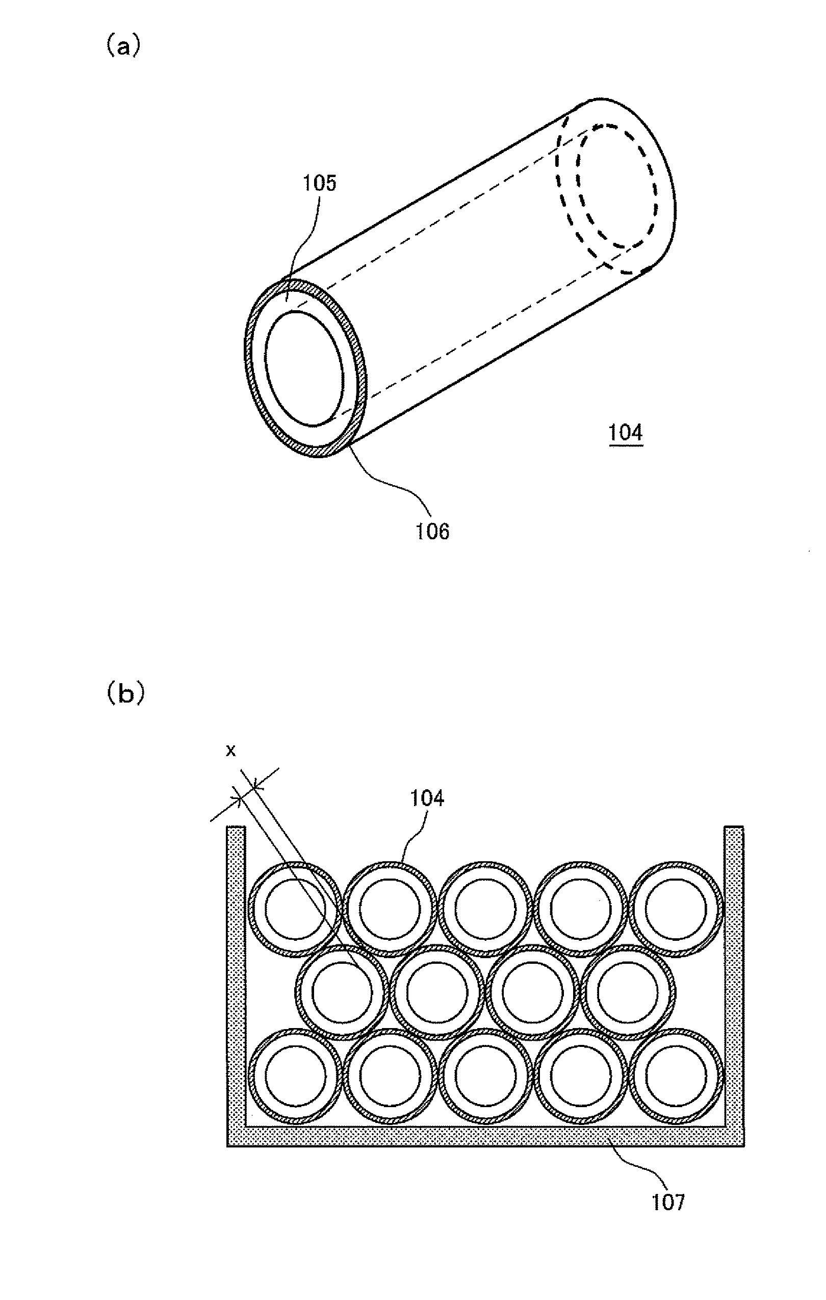
[0150]Embodiment 3 will be described with reference to FIG. 9. FIG. 9 is a diagram showing a method of manufacturing a battery case of Embodiment 3. FIG. 9(a) shows quadrilateral columnar material 110 as a rod into which one unit cell can be inserted. FIG. 9(b) is a side view showing a battery case in which quadrilateral columnar materials 110 are stacked, in view of the direction in which the unit cells are to be inserted.
[0151]As shown in FIG. 9(a), quadrilateral columnar material 110 includes: core 111 as a quadrilateral cylinder having circular hole 102a; convex portions 112 formed on the respective centers of a pair of side walls of core 111, convex portions 112 being along a longitudinal direction of core 111; concave portions 113 at which four edges of core 111 are notched along the longitudinal direction of core 111; and connection layer 106 covering core 111. Concave portion 113 is formed such that one convex portion 112 is fitted in a part configured with two concave porti...
PUM
| Property | Measurement | Unit |
|---|---|---|
| thermal conductivity | aaaaa | aaaaa |
| thermal conductivity | aaaaa | aaaaa |
| diameter | aaaaa | aaaaa |
Abstract
Description
Claims
Application Information
 - R&D
- Intellectual Property
- Life Sciences
- Materials
- Tech Scout
- Unparalleled Data Quality
- Higher Quality Content
- 60% Fewer Hallucinations
Browse by: Latest US Patents, China's latest patents, Technical Efficacy Thesaurus, Application Domain, Technology Topic, Popular Technical Reports.
© 2025 PatSnap. All rights reserved.Legal|Privacy policy|Modern Slavery Act Transparency Statement|Sitemap|About US| Contact US: help@patsnap.com


