Display panel having retaining wall and display device having the same

a technology of display panel and retaining wall, applied in the field of display panel packaging, to achieve the effect of effectively preventing display abnormality of display panel

Active Publication Date: 2020-11-24
HKC CORP LTD
View PDF5 Cites 0 Cited by
  • Summary
  • Abstract
  • Description
  • Claims
  • Application Information

AI Technical Summary

Benefits of technology

[0006]The main purpose of the present application is to provide a display panel and a display device, aiming at preventing display abnormality of the display panel.
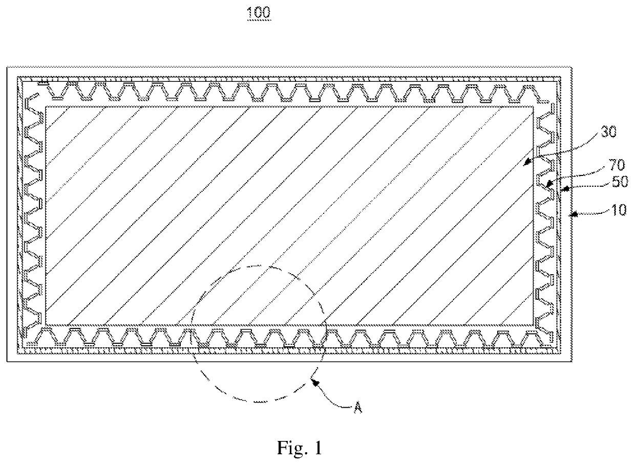
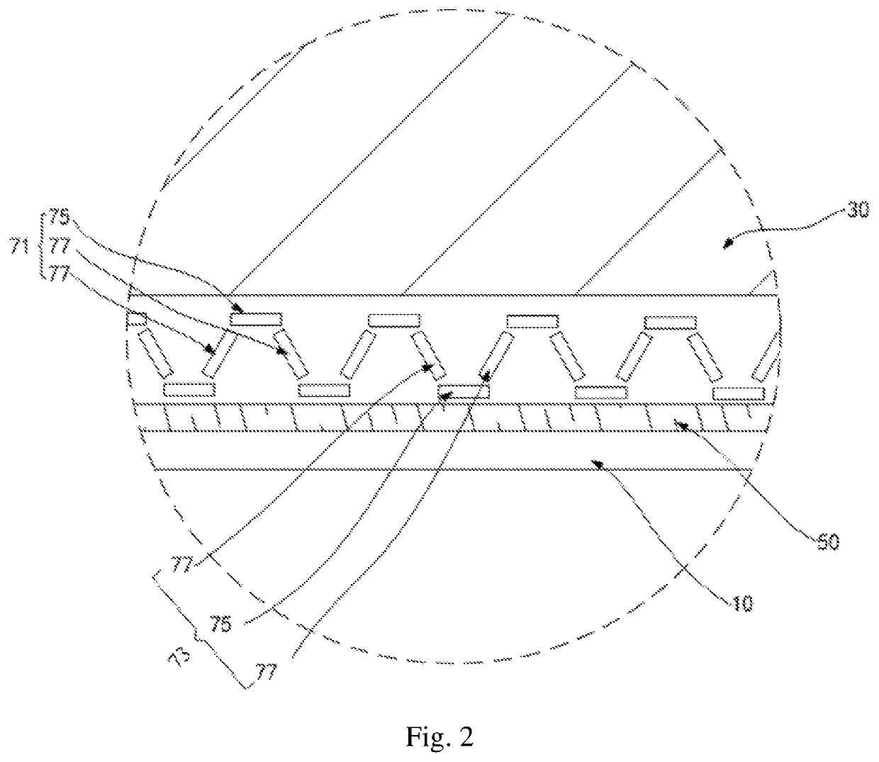
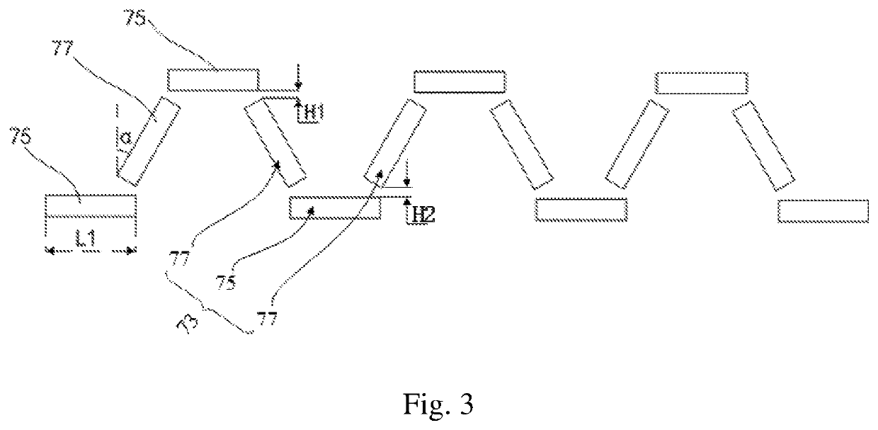
[0036]According to the technical solutions of the present application, by arranging the retaining wall between the alignment film and the sealant, alignment film liquid is prevented from making contact with the sealant. At the same time, by making the retaining wall consist of the plurality of sections of sub-retaining walls which are arranged to form the protrusions and the depressions, after flowing to the protrusions, the alignment film liquid then flows to the depressions through the sub-retaining walls beside the protrusions and converges at the depressions; in this way, the alignment film liquid does not flow back, so that the display of the active area is normal. Furthermore, the alignment film liquid will not come into contact with the sealant because of the blocking and convergence of the protrusions and the depressions. As a result, display abnormality of the display panel can be effectively prevented.

Problems solved by technology

However, while preventing the outflow of the liquid alignment film material, the vertical retaining wall also causes the liquid alignment film material to impact the retaining wall to generate backflow, so that abnormal display is caused on the peripheral edges of the display panel due to the lack of alignment film material at the edge of the substrate, as well as in the active area due to the backflow of the liquid alignment film material.

Method used


Image

  • Display panel having retaining wall and display device having the same
  • Display panel having retaining wall and display device having the same
  • Display panel having retaining wall and display device having the same

Examples


Embodiment Construction

>[0043]The technical solutions in the embodiments of the present application will be clearly and completely described hereafter in reference to the drawings in the embodiments of the present application. It is apparent that the described embodiments are merely a part of embodiments rather than all the embodiments of the present application. All the other embodiments obtained by the artisans concerned on the basis of the embodiments in the present application without creative efforts fall within the scope of claims of the present application.

[0044]It is to be understood that, all of the directional instructions in the exemplary embodiments of the present disclosure (such as top, down, left, right, front, back) can only be used for explaining relative position relations, moving condition of the elements under a special form (referring to figures), and so on, if the special form changes, the directional instructions changes accordingly.

[0045]In this application, unless otherwise stated...


PUM

PropertyMeasurementUnit
included angleaaaaaaaaaa
length L1aaaaaaaaaa
vertical distance H1aaaaaaaaaa

Abstract

The application discloses a display panel and a display device. The display panel comprises a substrate comprising an active area and a non-display area surrounding the active area; an alignment film arranged in the active area; a sealant arranged in the non-display area; and at least one row of retaining wall arranged between the alignment film and the sealant, and the retaining wall comprises a plurality of sections of sub-retaining walls which are arranged at intervals to form protrusions and depressions.

Description

CROSS REFERENCE TO RELATED APPLICATIONS[0001]This application is a Continuation Application of PCT Application No. PCT / CN2018 / 122088 filed on Dec. 19, 2018, which claims the benefit of Chinese patent application No. 201822035652.5 titled “DISPLAY PANEL AND DISPLAY DEVICE” applied on Dec. 5, 2018, the disclosure of which is incorporated herein by reference in its entirety.FIELD OF THE DISCLOSURE[0002]The present application relates to the technical field of display panel packaging, in particular to a display panel and a display device using the display panel.BACKGROUND OF THE DISCLOSURE[0003]The statements herein merely provide background information related to the present application and do not necessarily constitute prior art.[0004]A liquid crystal display comprises an upper substrate and a lower substrate which are oppositely arranged, wherein the upper substrate mainly consists of a matrix composed of red, green and blue color resistors and indium tin oxide (ITO) serving as a com...

Claims


Application Information

Patent Timeline
Patent Type & Authority Patents(United States)
IPC IPC(8): G02F1/1339G02F1/1337
CPCG02F1/133723G02F1/13394G02F2001/13398G02F1/1339G02F1/1337G02F1/133388G02F1/13398
Inventor WU, CHUAN
Owner HKC CORP LTD
Why Eureka
Try Eureka