
Joystick for controlling an aircraft

a joystick and aircraft technology, applied in the direction of mechanical control devices, manual control with single controlling member, instruments, etc., can solve the problems of deteriorating the behaviour of the joystick, inability to precisely generate force feedback, passive devices are often sources of non-linear elastic force, etc., to achieve no risk of jamming, and simple

Active Publication Date: 2017-01-24
SAFRAN ELECTRONICS & DEFENSE
View PDF7 Cites 0 Cited by
  • Summary
  • Abstract
  • Description
  • Claims
  • Application Information

AI Technical Summary

Benefits of technology

The technical effects of this patent are to provide a simple and robust joystick for controlling an aircraft that is free from jamming and can provide accurate and stable return forces. Additionally, the joint structure allows for the integration of sensors within the articulation.

Problems solved by technology

However, the existence of friction in existing mechanisms tends to deteriorate behaviour of the joystick as is sensed by the pilot.
In particular, when the joystick is equipped with force sensors, friction occurs between the pieces of the mechanism causing bias and hysteresis in the measurements made by these sensors, such that the force feedback cannot be generated precisely.
Apart from friction problems, the usual passive devices are often a source of non-linearity of the elastic force, or even of coupling force, caused by displacement of an axis on the force sensed on the normally independent second axis.

Method used


Image

  • Joystick for controlling an aircraft
  • Joystick for controlling an aircraft
  • Joystick for controlling an aircraft

Examples


first embodiment

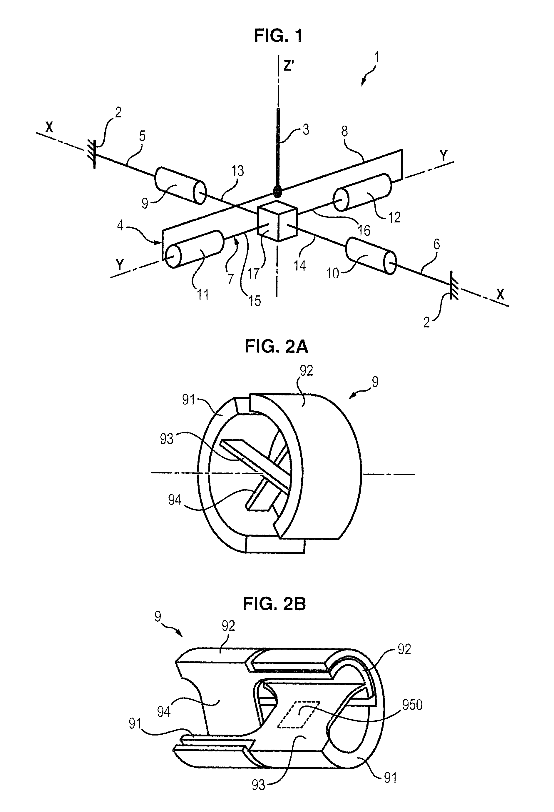
[0050]FIG. 1 schematically illustrates a joystick 1 according to the invention.

[0051]The joystick 1 comprises a frame 2 intended for example to be integrated into a pilot's seat armrest, a lever 3 mounted mobile in rotation relative to the frame 2, and a mechanical linking assembly 4 of the lever on the frame for generating a return of force on the lever according to two axes of rotation X and Y.

[0052]The lever 3 has a general elongated form according to a longitudinal direction (axis Z′).

[0053]The mechanical linking assembly 4 comprises two support pieces 5 and 6 mounted fixed relative to the frame 2, an intermediate piece 7 mounted mobile in rotation relative to the support pieces 5 and 6 about the first axis X, and a connecting piece 8 on which is fixed the lever 3, the connecting piece 8 being mounted mobile in rotation relative to the intermediate piece 7 about the second axis Y. The second axis Y is perpendicular to the first axis X. Also, when the lever 3 is in neutral positi...

second embodiment

[0104]FIG. 10 schematically illustrates a joystick 1 in keeping with the invention.

[0105]This second embodiment is identical to the first embodiment, except that the first pivot joint 9 and the second pivot joint 10 have been replaced by a first chain of pivot joints 9, 109, 209, 309 and a second chain of pivot joints 10, 110, 210, 310 mounted between the support pieces 2 and the intermediate piece 7.

[0106]Similarly, the third pivot joint 11 and the fourth pivot joint 12 have been replaced by a third chain of pivot joints 11, 111, 211, 311 and a fourth chain of pivot joints 12, 112, 212, 312 mounted between the intermediate piece 7 and the connecting piece 8.

[0107]In the example shown in FIG. 10, each chain of pivot joints comprises four pivot joints mounted in series, including:[0108]two pivot joints mobile in rotation from a pre-stressed position according to a first direction of rotation only (arrow A), specifically the pivot joints 9, 109, 10, 110, 11, 111, 12, 112,[0109]two piv...


PUM


Abstract

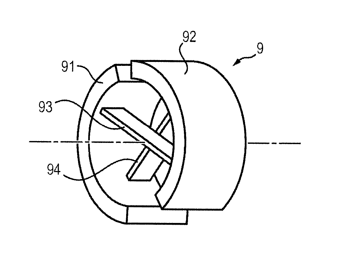
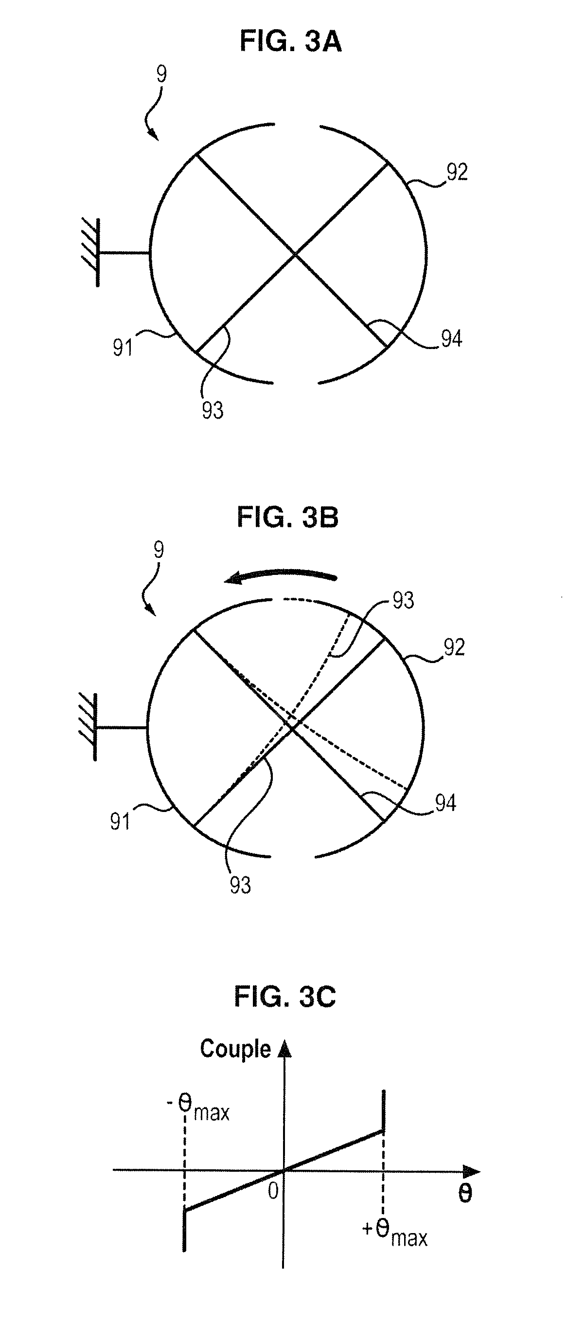
The invention relates to a joystick (1) for controlling an aircraft, including a frame (2), a lever (3), a mechanical linking assembly (4) for connecting the lever to the frame enabling a rotation of the lever (3) relative to the frame (2) about a first rotation axis (X), in which the mechanical linking assembly (4) includes a first pivot joint (9), the first pivot joint (9) including a first portion, a second portion movably mounted relative to the first portion, and at least two flexible blades, each flexible blade having an end that is attached to the first portion and another end that is attached to the second portion, and being resiliently deformable in order to enable a rotation of the second portion relative to the first portion along the first rotation axis (X) and to generate a return torque which hinders the rotation of the second portion relative to the first portion.

Description

FIELD OF THE INVENTION[0001]The invention relates to a joystick for controlling an aircraft.PRIOR ART[0002]Conventional aircraft are known, the flight controls of which are controlled by shifting a control lever connected mechanically to the orientable flight controls of the wings.[0003]Aircraft for which orientation of the flight controls is performed by electric and / or hydraulic actuators controlled by sensors for sensing movement of the lever are also known. On such devices, the lever is therefore not linked mechanically to the flight controls and the pilot does not sense any resistance from the lever, which lets him estimate movements of the flight controls and the forces they undergo.[0004]But some control levers are equipped with active and / or passive devices for simulating a feedback force on the lever.[0005]Also, in some planes equipped with electronic flight controls, the control stick has been replaced by a control device called a “joystick”. More compact than a convention...

Claims


Application Information

Patent Timeline
Patent Type & Authority Patents(United States)
IPC IPC(8): G05G1/08B64C13/04G05G5/03G05G1/04G05G9/047
CPCB64C13/04G05G1/04G05G5/03G05G9/047G05G2009/04766Y10T74/20474B64C13/0421
Inventor BUOY, FLORENCEMERLET, ETIENNEGORECKI, HERVE
Owner SAFRAN ELECTRONICS & DEFENSE
Learn More