Module for a modular conveyor belt

a conveyor belt and modular technology, applied in the field of modular conveyor belts, can solve the problems of plastic deformation, structural failure, and easy stress on the retainer, and achieve the effect of reducing the number of components and reducing the number of parts

Active Publication Date: 2017-01-24
LAITRAM LLC
View PDF33 Cites 8 Cited by
  • Summary
  • Abstract
  • Description
  • Claims
  • Application Information

AI Technical Summary

Benefits of technology

[0005]This invention provides a module for a modular conveyor belt which can prevent a hinge rod retainer from being damaged during the process of removing a hinge rod from the module.
[0009]The stopper can support the retainer such that a prying force can be applied to the retainer opposite the stopper without producing any substantial increase in bending stresses in the retainer. The dimensions of the stopper are selected such that the stresses within the retainer when the retainer is supported by the stopper are within the design stress of the retainer. The design stress of the retainer refers to a stress at which the retainer does not undergo structural failure, i.e., break, and at which any plastic deformation of the retainer is of an extent that when a force pressing the retainer towards the stopper is released, the retainer can return to a position in which the free end of the retainer can prevent a hinge rod from being withdrawn from the bore in the module. As such, the stopper can prevent the retainer from being damaged by a technician during the process of removing a hinge rod from the module, whereby the module can be used for long periods without needing to be replaced.
[0013]According to still another form of the present invention, a method of removing a hinge rod from a conveyor belt module includes applying a force to a retainer of the module to bend the retainer from a first position in which the retainer lies across a path of axial movement of the hinge rod to a second position in which the retainer lies outside a path of axial movement of the hinge rod and in which a bottom surface of the retainer contacts an upper surface of a stopper opposing the bottom surface of the retainer at a point in a middle 50% of a length of the retainer without the retainer exceeds its design stress, and moving the hinge rod in its axial direction to pass the hinge rod over the retainer.

Problems solved by technology

This method of bending the retainer may not cause a problem if the prying force is exerted near the free end of the retainer, but if the prying force is applied near the fixed end or near the midportion of the retainer, the retainer can easily be subjected to stresses which exceed its design stress.
As a result, the retainer may undergo plastic deformation of an extent such that it cannot return to a position in which it prevents retraction of a hinge rod, and it may even undergo structural failure, i.e., it may break.
In either case, the retainer can no longer retain a hinge rod in the conveyor belt.

Method used


Image

  • Module for a modular conveyor belt
  • Module for a modular conveyor belt
  • Module for a modular conveyor belt

Examples


Embodiment Construction

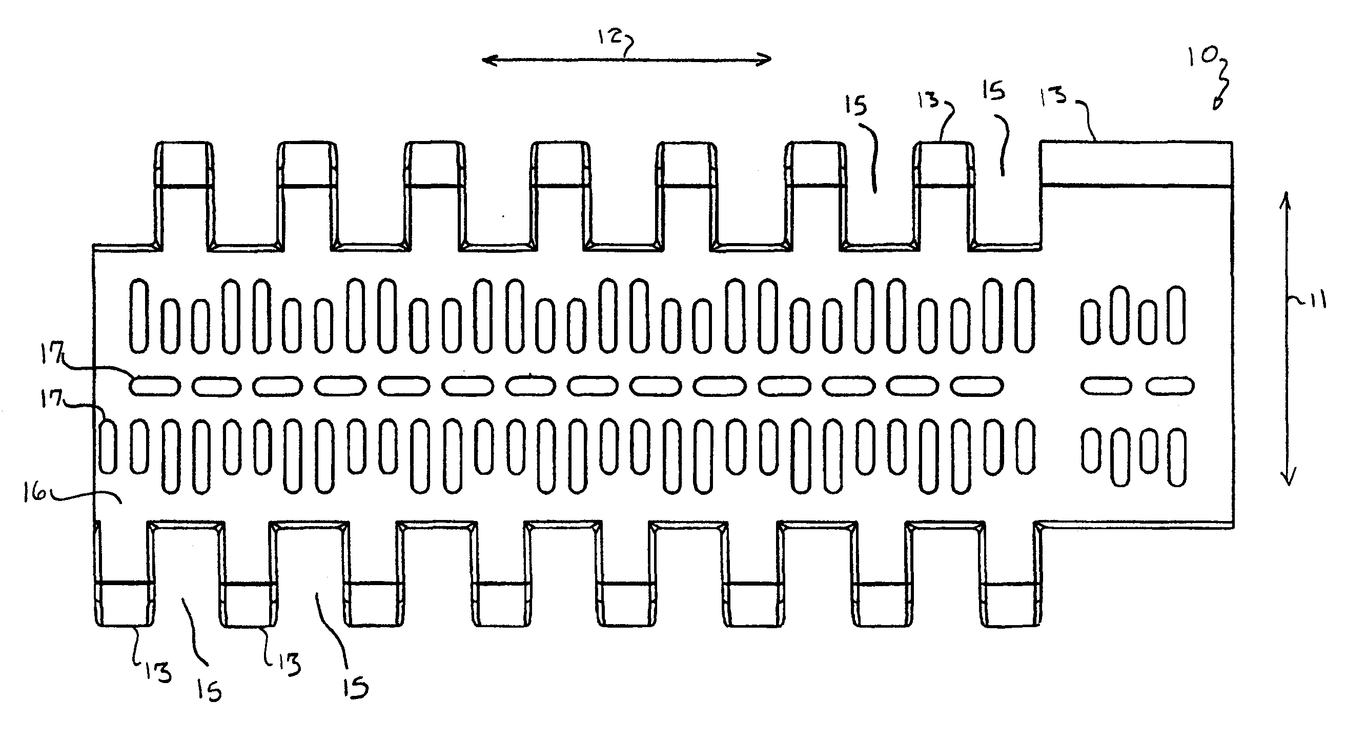
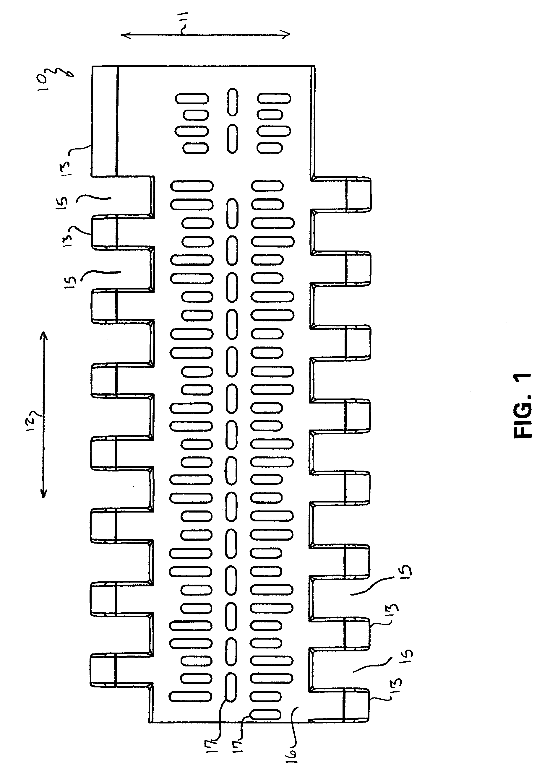
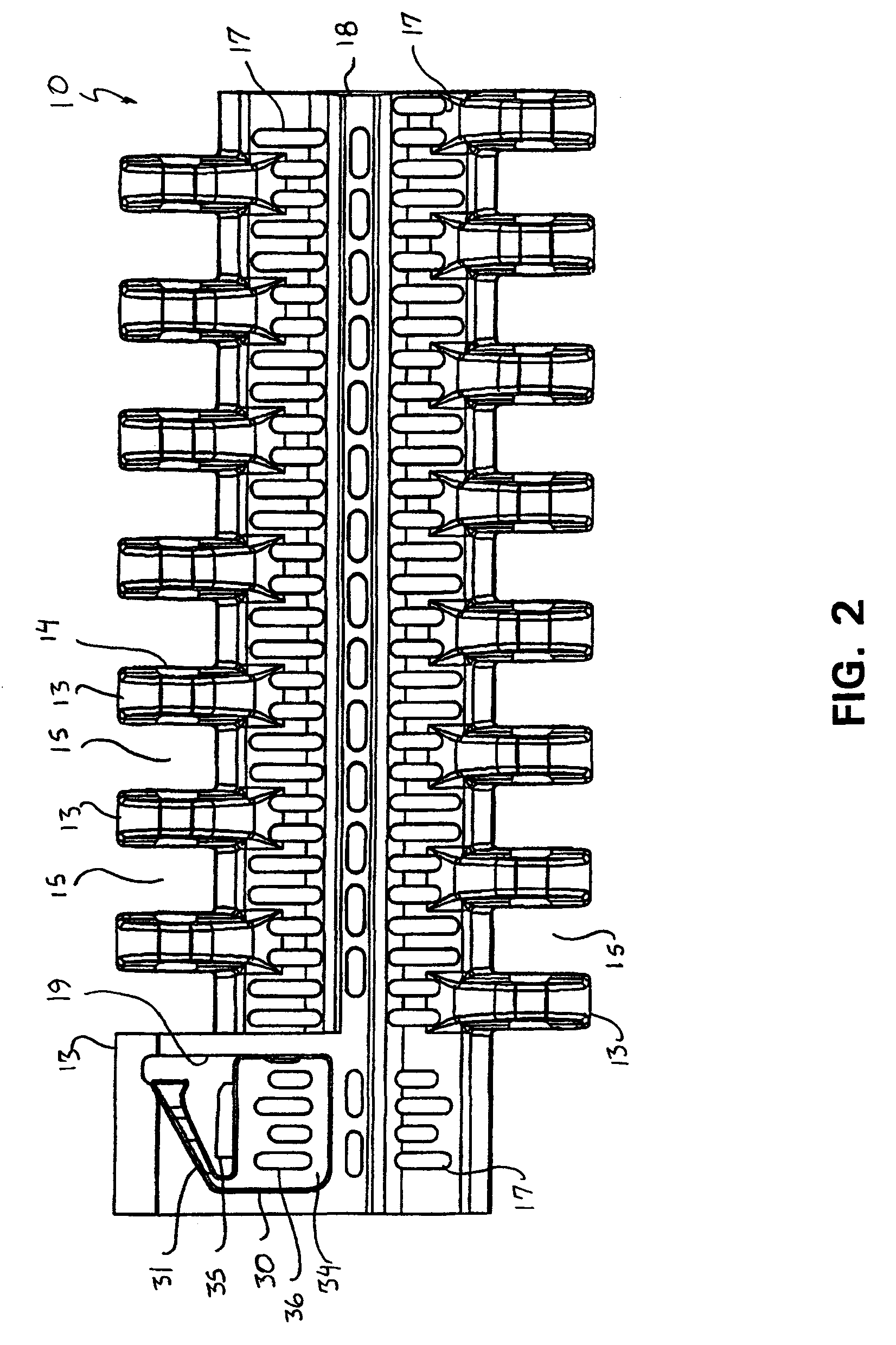
[0025]FIGS. 1 and 2 are top and bottom plan views, respectively, of an embodiment of a module 10 for a modular conveyor belt according to the present invention. As long as the module 10 has a retainer which can be flexed between a position in which it can prevent retraction of a hinge rod from the module and a position in which it permits a hinge rod to be retracted from the module, there are no particular restrictions on the shape of the module. For example, it can have the same overall shape as a wide variety of existing modules for modular conveyor belts. As such, the shape of the module 10 shown in FIGS. 1 and 2 is merely one example of many possible shapes. The illustrated module 10 has the same overall shape as that of a Series 800 Perforated Flat Top 295 module sold by Intralox, L.L.C. of Harahan, La. This module 10 has a generally rectangular outer periphery as viewed in plan and includes first and second lengthwise ends and first and second widthwise ends. In this descripti...


PUM

PropertyMeasurementUnit
heightaaaaaaaaaa
widthaaaaaaaaaa
lengthaaaaaaaaaa

Abstract

A module for a modular conveyor belt includes a flexible retainer for retaining a hinge rod in a bore of the module. A stopper limits the bending movement of the retainer and supports the midportion of the retainer to prevent stresses generated in the retainer from exceeding its design stress.

Description

BACKGROUND OF THE INVENTION[0001]This invention relates to a module for a modular conveyor belt which has a retainer for retaining a hinge rod in the module and which enables a hinge rod to be retracted from the module without damaging the retainer.[0002]A modular conveyor belt is a conveyor belt formed from a plurality of units (referred to as modules) pivotably connected to each other end to end in series. Modular conveyor belts are popular in the product handling industry because the length of such conveyor belts can be readily adjusted by varying the number of modules making up the conveyor belts. Furthermore, a modular conveyor belt is easy to repair when worn or damaged by simply replacing any worn or damaged modules without it being necessary to replace the entire conveyor belt.[0003]The modules forming a modular conveyor belt are pivotably connected in series by elongated hinge rods which pass through aligned bores formed in the modules. Various means have been employed to p...

Claims


Application Information

Patent Timeline
Patent Type & Authority Patents(United States)
IPC IPC(8): B65G17/40B65G17/38B65G17/06B65G17/08
CPCB65G17/40B65G17/08B65G2207/12Y10T29/49815
Inventor WUNSCH, PHILIP J.
Owner LAITRAM LLC
Why Eureka
Try Eureka