Method for producing a customized orthodontic appliance

a technology of customizing and producing orthodontic appliances, applied in the field of self-ligating orthodontic bracket systems, can solve the problems of not preventing the archwire from being readily removed from the bracket slot, and achieve the effects of low cost, easy production and industrial scal

Active Publication Date: 2017-01-31
ORTHOAMERICA HLDG LLC
View PDF400 Cites 27 Cited by
  • Summary
  • Abstract
  • Description
  • Claims
  • Application Information

AI Technical Summary

Benefits of technology

[0012]Also, note that the cylindrical recess may include additional features or mechanisms that prevent the rotatable member from freely rotating within the cylindrical recess. In one or more embodiments, a circular cross section (perpendicular to the central axis of the cylindrical recess) may be slightly out of round in various places to frictionally engage adjacent surfaces of the rotatable member for assisting in maintaining the slot coverable extensions in one or more predetermined orientations relative to the slot. In one or more embodiments of the bracket, the cylindrical recess and the rotatable member may include interlocking elements that substantially restrict the rotation of the rotatable member to discrete and predetermined angular orientations about the central axis. Such interlocking elements may provide a ratchet mechanism, or alternatively interlocking shapes wherein a first shaped element (e.g., on the cylindrical portion of the rotatable member or a wall portion of the cylindrical recess) mates or interlocks with compatibly one or more shaped elements (on the other of the rotatable member or a wall of the cylindrical recess) dispersed at discrete angular positions about the central axis for restricting rotation of the rotatable member from one of these positions to another. Note that such interlocking elements may allow the rotatable member to rotate in both a clockwise and a counter clockwise direction when a sufficient predetermined directional force(s) is applied for disengaging the interlocking elements from a first position and interlocking at a second position.
[0056]In a preferred embodiment of a ligual based bracket system that facilitates a self-ligating bracket to be employed, each bracket is fixed to a surface of a tooth by a bracket bonding pad.

Problems solved by technology

In particular, such extensions, when rotated to occlude at least a portion of the slot opening thereby preventing an archwire residing in the bracket slot from exiting therefrom, and when rotated out of the slot opening, these extensions do not prevent the archwire from being readily removed from the bracket slot, e.g., by an orthodontist or technician.

Method used


Image

  • Method for producing a customized orthodontic appliance
  • Method for producing a customized orthodontic appliance
  • Method for producing a customized orthodontic appliance

Examples


Embodiment Construction

is given with reference to the figures which depict:

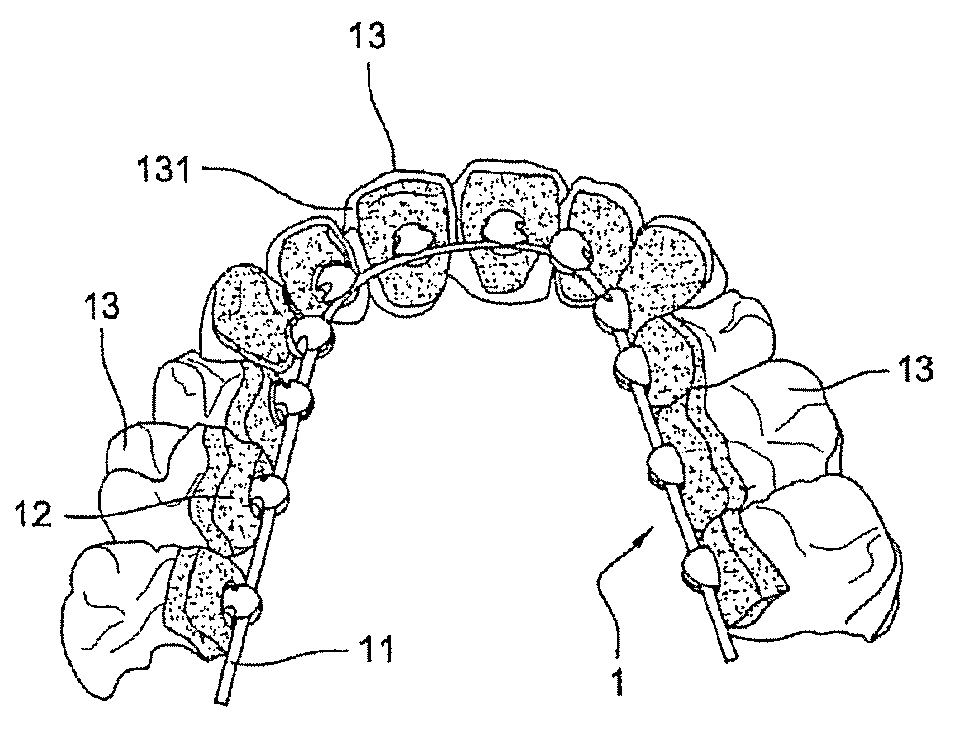
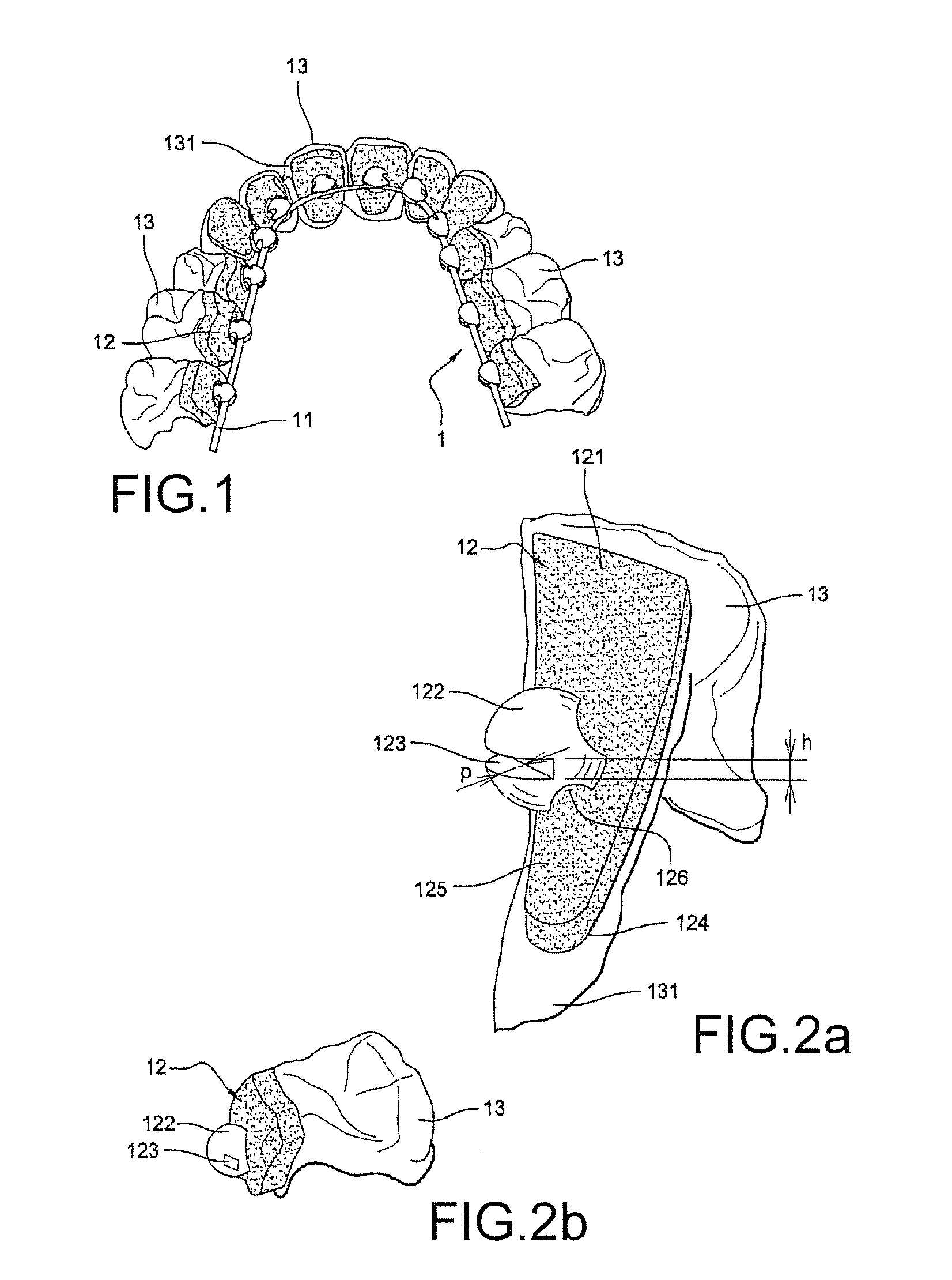
[0063]FIG. 1: a view, from the inside of the mouth, of a lingual orthodontic appliance on a dental arch of a patient,

[0064]FIG. 2a: a perspective depiction of a bracket according to the invention attached to a surface of a tooth,

[0065]FIG. 2b: a perspective depiction of a bracket according to the invention attached to a surface of a tooth, and comprising a tube,

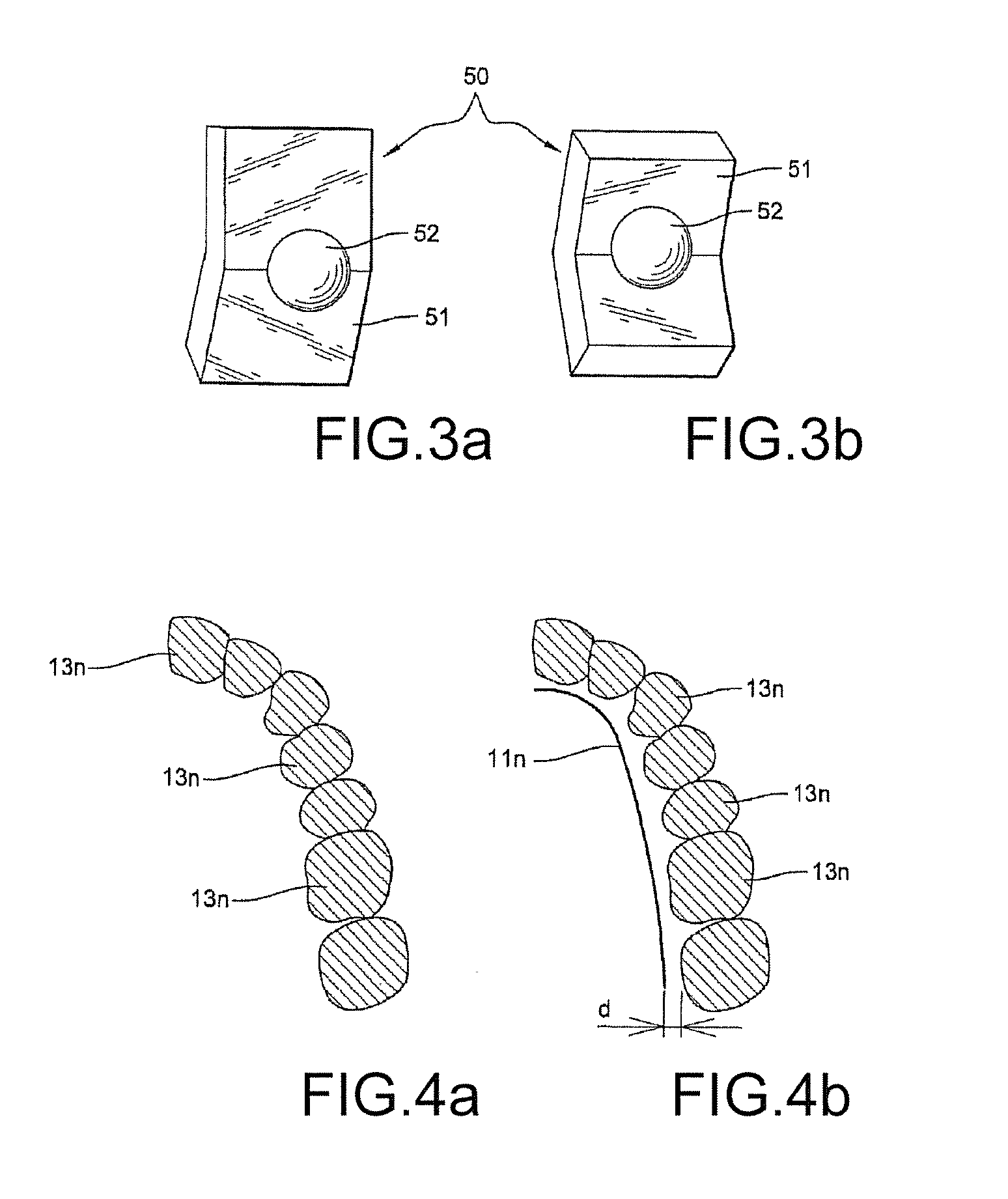
[0066]FIG. 3a: a perspective view of a first example of a blank for producing a bracket according to the invention,

[0067]FIG. 3b: a perspective view of a second example of a blank for producing a bracket according to the invention,

[0068]FIG. 4a: an illustration of a numerical representation of a cross section of a dental arch in a plane of the orthodontic archwire,

[0069]FIG. 4b: an illustration of a numerical representation of the positioning of an orthodontic archwire for a cross section of a dental arch in a plane of the orthodontic archwire, after a second step of the met...


PUM


Abstract

The present disclosure is directed, at least in part, to a self ligating orthodontic bracket system that includes a rotatable member for securing an archwire within a slot of a bracket. Embodiments of the orthodontic bracket system disclosed herein include a bracket body containing the archwire slot as well as tie wings for attaching various orthodontic devices (e.g., elastomeric bands) to the bracket. The rotatable member is rotatable in a first direction (e.g., counter clockwise) relative to a body of the bracket for securing or locking the archwire within the slot, and for rotating in an opposite direction (e.g., a clockwise direction) relative to the bracket body for unsecuring or unlocking the archwire so that it is substantially unrestrained from exiting the slot. Other embodiments include an orthodontic appliance and method of producing and using the same, and preferably employed in a lingual orthodontic system, that includes friction reducing features between an interior of an archwire slot portion of the appliance and an archwire placed within the archwire slot.

Description

REFERENCE TO RELATED APPLICATIONS[0001]This application is a continuation of U.S. patent application Ser. No. 13 / 762,455, filed on Feb. 8, 2013, which is a continuation-in-part application to and claims priority to U.S. patent application Ser. No. 13 / 117,085, filed May 26, 2011 (now U.S. Pat. No. 8,376,739, issued Feb. 19, 2013), which claims priority to U.S. Provisional Patent Application No. 61 / 518,927, filed May 12, 2011; both of which are incorporated fully herein by this reference. This application being a continuation of Ser. No. 13 / 762,455, filed on Feb. 8, 2013, which is a continuation-in-part application of U.S. patent application Ser. No. 12 / 937,588 filed on Dec. 15, 2010 (now U.S. Pat. No. 8,371,847, issued Feb. 12, 2013); this application being a continuation of Ser. No. 13 / 762,455, which is a continuation-in-part of U.S. patent application Ser. No. 13 / 595,548, filed Aug. 27, 2012 (now U.S. Pat. No. 8,585,399, issued Nov. 19, 2013), which is a continuation of U.S. patent...

Claims


Application Information

Patent Timeline
Patent Type & Authority Patents(United States)
IPC IPC(8): A61C3/00A61C7/28A61C7/00A61C7/16A61C7/14
CPCA61C7/002A61C7/143A61C7/16A61C7/28A61C7/285A61C7/141A61C7/145
Inventor GUALANO, CHRISTOPHE
Owner ORTHOAMERICA HLDG LLC
Why Eureka
Try Eureka