Selectively lockable torque-limiting mechanism

a torque limiter and lockable technology, applied in the field of tools, can solve the problems of internal components breaking internal components slipping, etc., and achieve the effects of reducing variation, avoiding significant recoil or snapping, and reducing wear

Active Publication Date: 2017-01-31
GAUTHIER BIOMEDICAL
View PDF49 Cites 3 Cited by
  • Summary
  • Abstract
  • Description
  • Claims
  • Application Information

AI Technical Summary

Benefits of technology

[0009]According to a one aspect of the present invention, a torque-limiting device for use in hand-held and power tools is provided in which the torque-limiting device includes a number of rolling ball bearings disposed partially within opposed pairs of recesses located in a pair of opposed gears that, in conjunction with springs acting on the gears and ball bearings, are utilized to control the movement and resistance to movement of the mechanism. The recesses in one of the gears are connected by a raceway along which the bearings can move between recesses when the mechanism is in operation. The use of the ball bearings and a raceway on one of the gears that the ball bearings can move along between the recesses enables the mechanism to be operated in a manner that greatly reduces the amount of variation over time of the preset torque values for the mechanism by reducing the wear experienced by the internal components controlling the actuating of the mechanism, and by avoiding the significant recoil or snap experienced by prior art mechanisms. This construction also greatly reduces the effects of varying levels of friction present in prior art mechanism by using ball bearings as the main friction generating members in the mechanism. The shape of the bearings creates much less overall friction, as well as a relatively constant amount of friction over extended periods of use of the mechanism, without the need for significant amounts of lubricants within the mechanism.

Problems solved by technology

With regard to hand-held and powered tools used to drive features into or out of an item, especially those used in medical applications, there are several common problems associated with tools incorporating existing torque-limiting devices.
These problems include loss of consistent torque value after repeated autoclave sterilization cycles, internal components breaking due to high forces and loads on internal cams and gears, inconsistent torque values due to wear on internal components, a strong recoil or snap when set at higher torque values, and difficulty in servicing the mechanism.
However, due to the cleaning and / or sterilization of tools including devices of this type, each sterilization cycle causes an inherent loss of the lubrication in the mechanism.
This movement of the locking surfaces 106 into engagement with one another necessarily creates vibrations in the mechanism which are transmitted through the mechanism and the tool incorporating the mechanism to the fastener and / or the person on which the device is being utilized.
In many situations, these vibrations are highly undesirable.
Also, the stress exerted on the surfaces 106 as they strike one another also leads to fracturing or chipping of the teeth 102, lessening the useful life of the mechanism.
When the teeth 102 are chipped, this additional material can also collect on the sliding surfaces 104 of the teeth 102, thereby causing even more inconsistent torque values for the mechanism.
The design of each of these prior art calibration nut assemblies increases the complexity of the overall mechanism, and provides an additional manner in which the mechanism can break down.

Method used


Image

  • Selectively lockable torque-limiting mechanism
  • Selectively lockable torque-limiting mechanism
  • Selectively lockable torque-limiting mechanism

Examples


Embodiment Construction

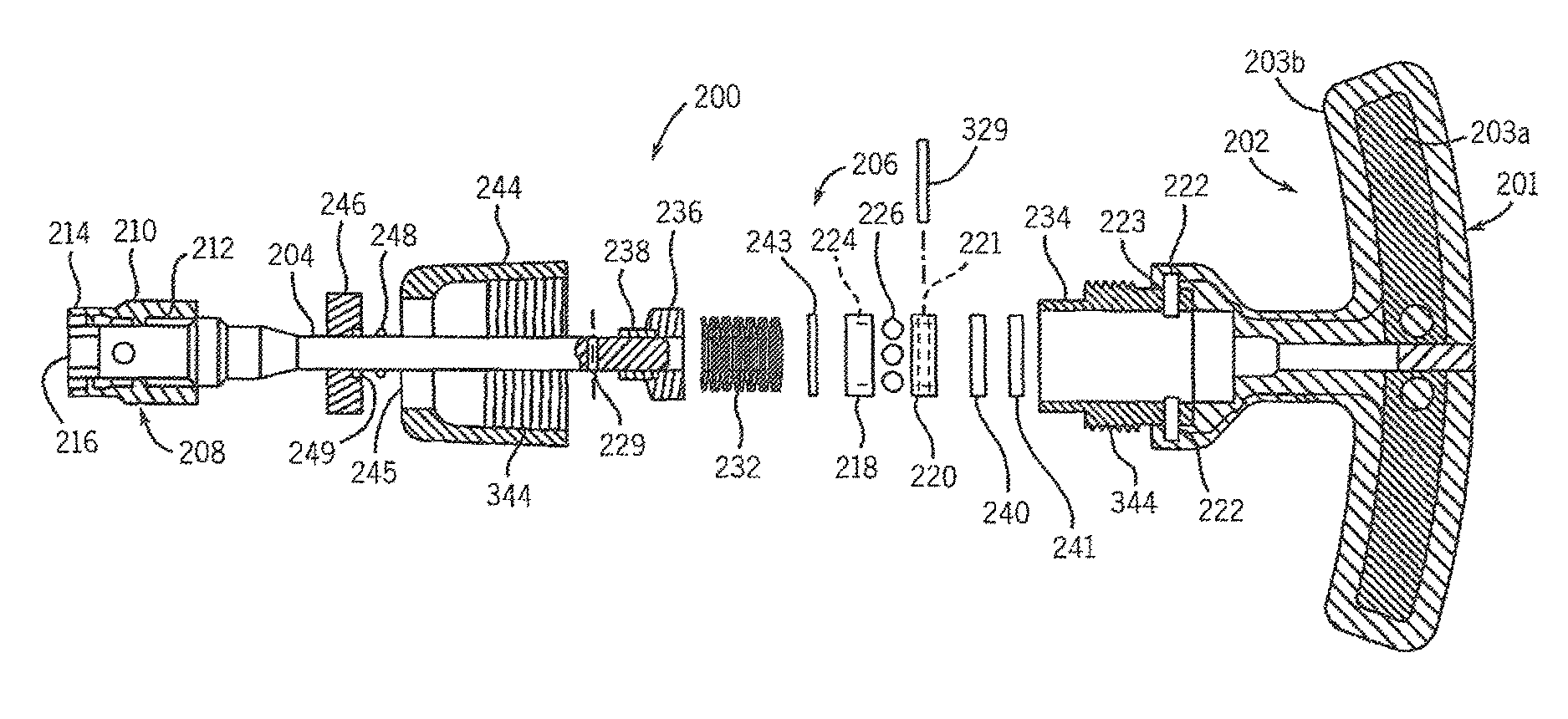
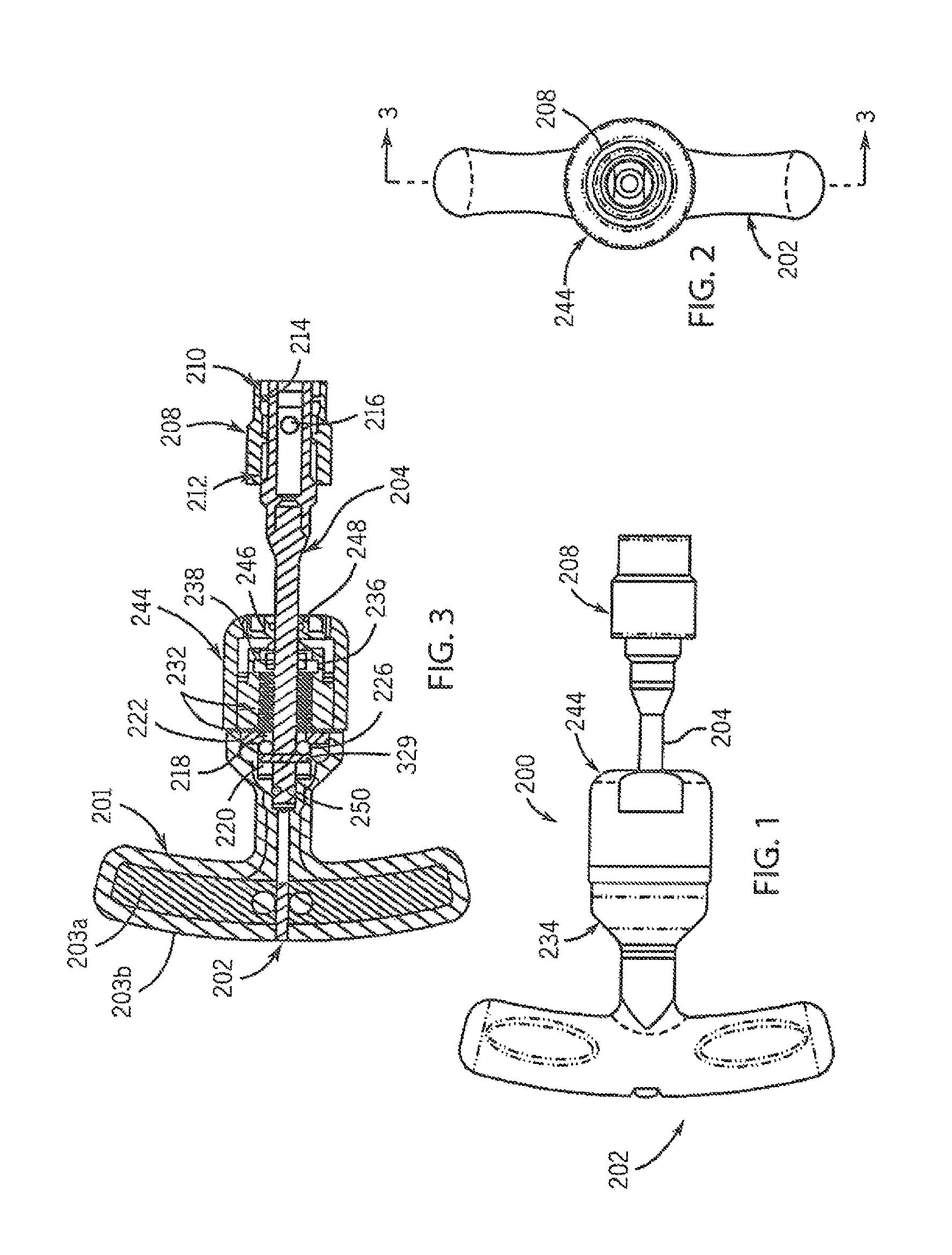
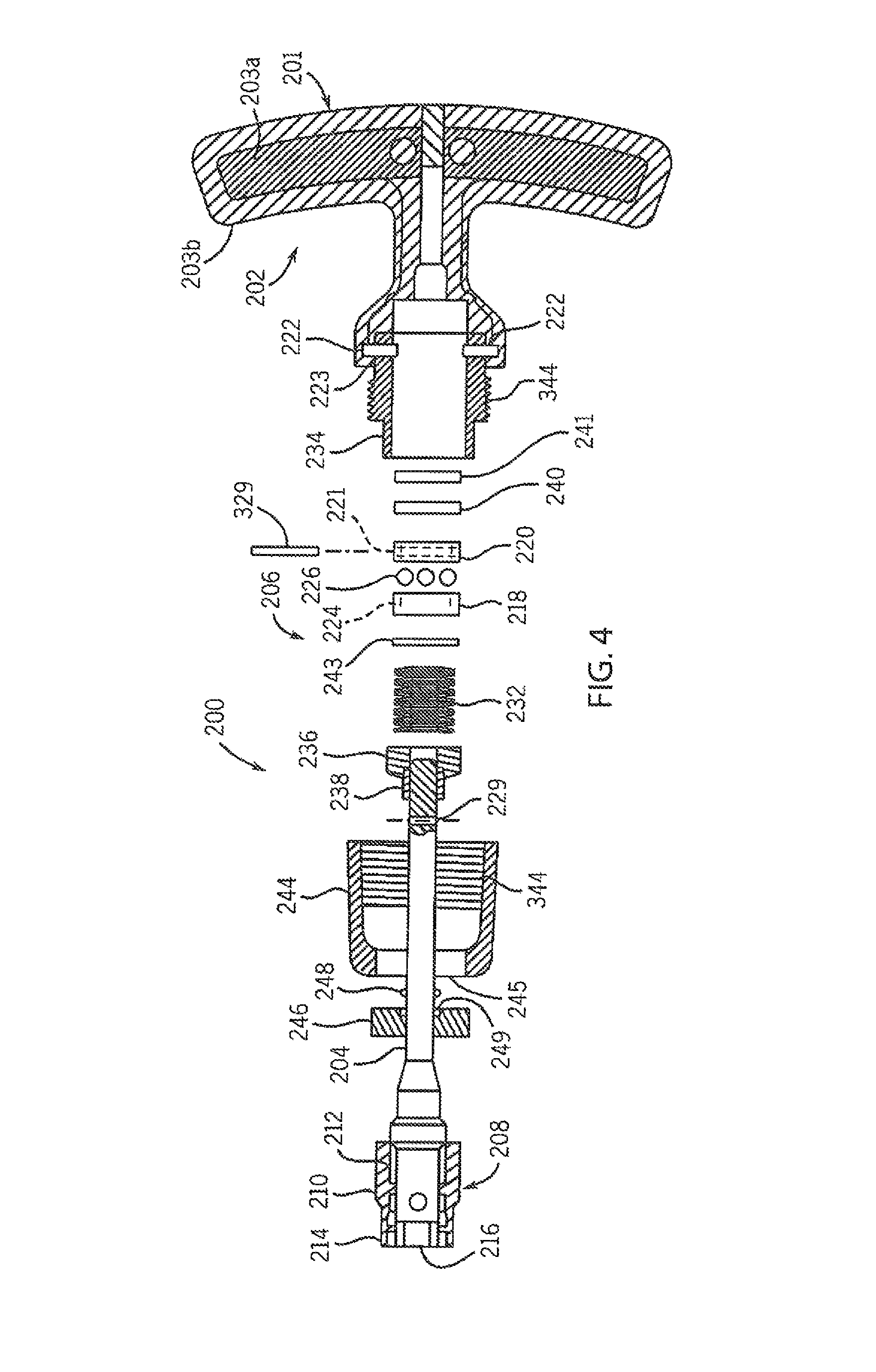
[0059]With reference now to the drawing figures in which like reference numerals designate like parts throughout the disclosure, a tool including a torque-limiting mechanism constructed according to the present invention is indicated generally at 200 in FIGS. 1-4. The tool 200 can be virtually any type of hand-held or power-driven tool that is used to apply torque to a driven member, e.g., a fastener, but in a preferred embodiment, is a hand-held torque wrench that includes a handle 202 with a gripping part 201 operatively connected to a drive body 204 extending outwardly from the handle 202 by the torque-limiting mechanism 206. The handle 202 is preferably formed of a suitably rigid, but relatively lightweight material, such as a light metal or plastic, to reduce the weight of the tool 200. Also, the handle 202 can be formed to have any desired configuration, and may include on the gripping part 201 an inner portion 203a formed of a more rigid material, and an outer portion 203b of...


PUM


Abstract

A tool including selectively operable torque-limiting mechanism is provided. The tool includes a housing, a torque-limiting mechanism disposed within the housing and including a first gear engaged with the housing and including a number of first recesses, a second gear rotatably disposed within the housing adjacent the first gear and including a number of second recesses, a number of bearings disposed between the first gear and the second gear partially within the first recesses and partially within the second recesses, and a variable force-applying assembly engaged with the first gear opposite the second gear, a drive body engaged with the second gear and extending outwardly from the housing, and a cover disposed around the housing and selectively engaged with the drive body to control the operation of the torque-limiting mechanism.

Description

CROSS-REFERENCE TO RELATED APPLICATIONS[0001]This application claims priority from U.S. Provisional Application Ser. No. 61 / 841,027, filed on Jun. 28, 2013, the entirety of which is expressly incorporated by reference herein.FIELD OF THE INVENTION[0002]The present invention relates to tools used to rotate and / or drive fasteners, and more specifically to a torque-limiting mechanism for use with these types of tools.BACKGROUND OF THE INVENTION[0003]With regard to hand-held and powered tools used to drive features into or out of an item, especially those used in medical applications, there are several common problems associated with tools incorporating existing torque-limiting devices. These problems include loss of consistent torque value after repeated autoclave sterilization cycles, internal components breaking due to high forces and loads on internal cams and gears, inconsistent torque values due to wear on internal components, a strong recoil or snap when set at higher torque valu...

Claims


Application Information

Patent Timeline
Patent Type & Authority Patents(United States)
IPC IPC(8): B25B23/157B25B23/142B25B23/14B25B21/00B25B15/02
CPCB25B23/1427B25B23/142B25B23/14B25B21/00B25B15/02B25B23/141
Inventor GAUTHIER, MICHAEL T.MILLER, ROBERT F.
Owner GAUTHIER BIOMEDICAL
Why Eureka
Try Eureka