Method and system for air traffic rerouting for airspace constraint resolution

a technology of air traffic and constraint resolution, applied in the field of trajectories for aircraft rerouting, can solve problems such as missing workable opportunities for more efficient flight routes

Active Publication Date: 2017-01-31
NASA
View PDF8 Cites 37 Cited by
  • Summary
  • Abstract
  • Description
  • Claims
  • Application Information

AI Technical Summary

Benefits of technology

[0008]The present invention provides an automated system for trajectory rerouting of aircraft for constraint avoidance. Constraints include special use airspace (SUA), weather, temporary flight restriction (TFR) airspace, and other limitations on the use of specified airspace. The system uses computer automation to continuously and automatically compute and propose time

Problems solved by technology

Weather is the leading cause of delay in the U.S. National Airspace System, and convective weather accounts for 60% of weather-related delays.
However, real-time automation that continuously searches for and proposes time- and fuel-eff

Method used


Image

  • Method and system for air traffic rerouting for airspace constraint resolution
  • Method and system for air traffic rerouting for airspace constraint resolution
  • Method and system for air traffic rerouting for airspace constraint resolution

Examples


Embodiment Construction

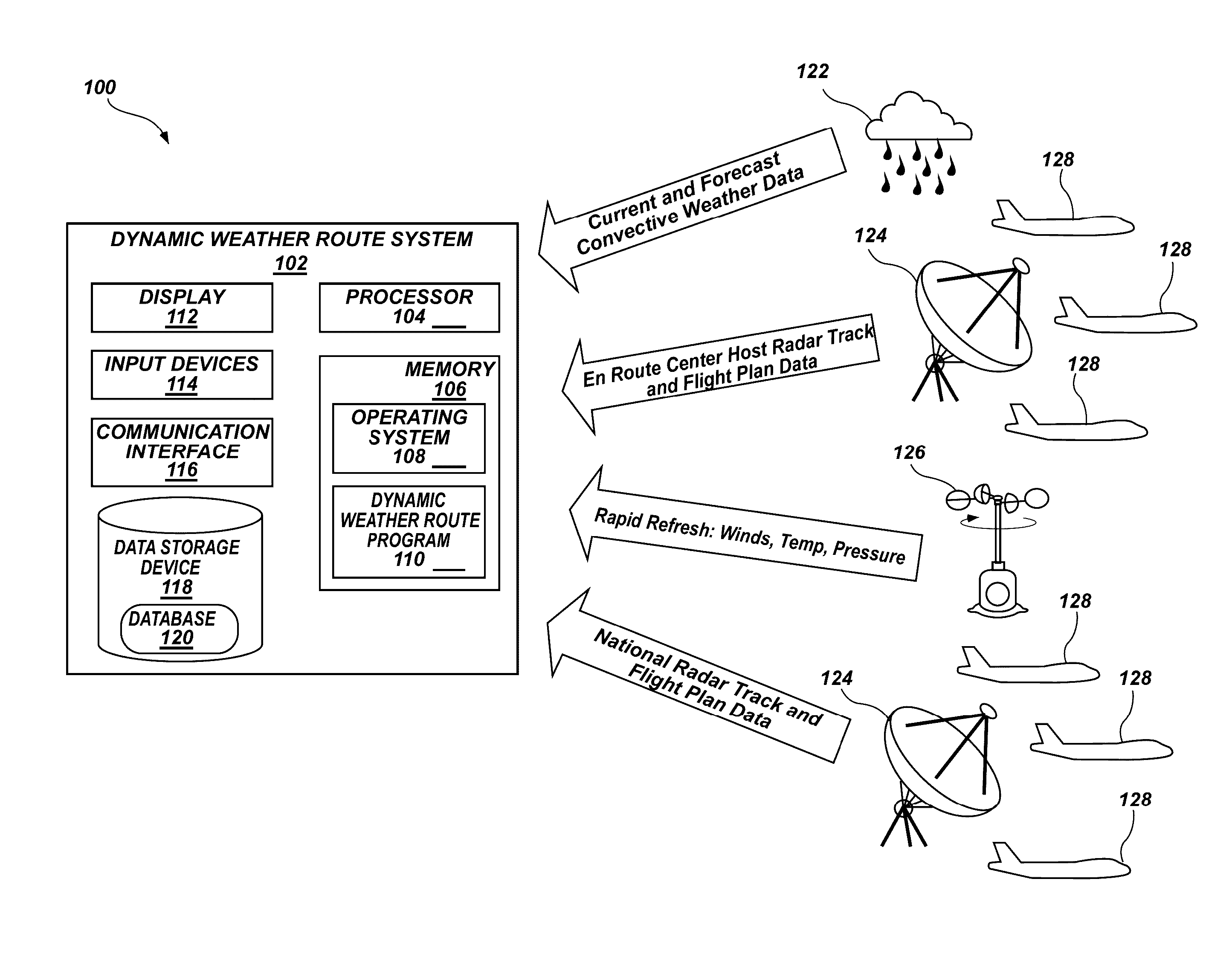
[0027]For the purposes of promoting an understanding of the principles in accordance with the disclosure, reference will now be made to the illustrative embodiments illustrated in the drawings, and specific language will be used to describe them. It will nevertheless be understood that no limitation of the scope of the disclosure is thereby intended. Any alterations and further modifications of the inventive features illustrated herein, and any additional applications of the principles of the disclosure as illustrated herein, which would normally occur to one skilled in the relevant art and having possession of this disclosure, are to be considered within the scope of the disclosure claimed.

[0028]It must be noted that, as used in this specification and the appended claims, the singular forms “a,”“an,” and “the” include plural referents unless the context clearly dictates otherwise. As used herein, the terms “comprising,”“including,”“having,”“containing,”“characterized by,” and gramm...


PUM


Abstract

A dynamic constraint avoidance route system automatically analyzes routes of aircraft flying, or to be flown, in or near constraint regions and attempts to find more time and fuel efficient reroutes around current and predicted constraints. The dynamic constraint avoidance route system continuously analyzes all flight routes and provides reroute advisories that are dynamically updated in real time. The dynamic constraint avoidance route system includes a graphical user interface that allows users to visualize, evaluate, modify if necessary, and implement proposed reroutes.

Description

CROSS-REFERENCE TO RELATED APPLICATIONS[0001]This application is a Continuation-In-Part of U.S. patent application Ser. No. 13 / 707,546, filed Dec. 6, 2012, which claims the benefit of U.S. Provisional Application Nos. and 61 / 567,604 and 61 / 664,489, filed Dec. 6, 2011 and Jun. 26, 2012, respectively, and this application also claims the benefit of U.S. Provisional Application No. 62 / 012,518, filed Jun. 16, 2014, which are all hereby incorporated by reference herein in their entireties.ORIGIN OF INVENTION[0002]The invention described herein was made in the performance of work under NASA contracts and by employees of the United States Government and is subject to the provisions of §20135(b) of the National Aeronautics and Space Act, Public Law 111-314, §3 (124 Stat. 3330, 51 U.S.C. Chapter 201), and 35 U.S.C. §202 Public Law 96-517, and may be manufactured and used by or for the Government for governmental purposes without payment of any royalties thereon or therefore.BACKGROUND OF INV...

Claims


Application Information

Patent Timeline
IPC IPC(8): G06F19/00G06G7/70G06G7/76G08G5/00
CPCG08G5/0039G08G5/0047G01C21/005G01C21/20G08G5/0013G08G5/0026G08G5/0043G08G5/006G08G5/0082G08G5/0091G08G5/0095
Inventor SHETH, KAPIL S.MCNALLY, B. DAVIDERZBERGER, HEINZMORANDO, ALEXANDER R.CLYMER, ALEXIS A.SHIH, FU-TAI
Owner NASA
Why Eureka
Try Eureka