Method and apparatus for cleaning a filter

a filter and air filter technology, applied in the field of air filter cleaner, can solve the problems of filter pore blockage with separated dirt and dust, filter blockage completely, inability to pass airflow, etc., and achieve the effect of cleaning the air filter quickly, efficiently, and minimal or no damage to the filter element itsel

Inactive Publication Date: 2017-02-07
ROYCE JOHN +1
View PDF22 Cites 2 Cited by
  • Summary
  • Abstract
  • Description
  • Claims
  • Application Information

AI Technical Summary

Benefits of technology

[0010]As a result of the above, there is a need in the art to provide a filter cleaner and method operable to clean an air filter quickly, efficiently and with minimal or no damage to the filter element itself.
[0013]By providing such an arrangement, both an airflow and mechanical agitation can be utilised to dislodge accumulated dirt and dust from a filter medium. This enables efficient cleaning of the filter and reduces the time required to perform a cleaning operation.

Problems solved by technology

Since a particulate filter comprises a semi-porous separation surface, over time the pores of the filter will become blocked with separated dirt and dust.
This increases the pressure drop across the filter and will, if unchecked, lead to the filter becoming completely blocked and unable to pass an airflow therethrough.
However, these arrangements are cumbersome and expensive to use.
Often, the size and expense of such equipment is prohibitive so it not practical to have on-site cleaning facilities at, for example, truck or bus depots.
This has obvious disadvantages in terms of delivery time and cost.
This can lead to damage to the filter media.
Furthermore, many of the above-disclosed arrangements are unsuitable for modern filter elements which comprise a pleated separation surface located within a cage element because they necessarily require unimpeded contact with the filter medium itself.

Method used


Image

  • Method and apparatus for cleaning a filter
  • Method and apparatus for cleaning a filter
  • Method and apparatus for cleaning a filter

Examples


Embodiment Construction

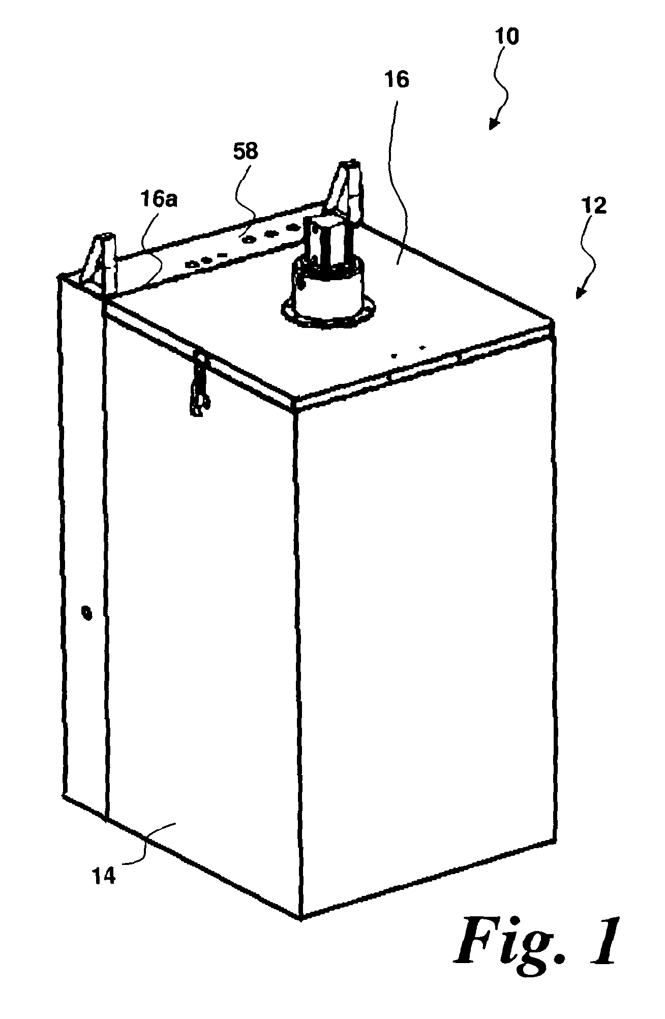
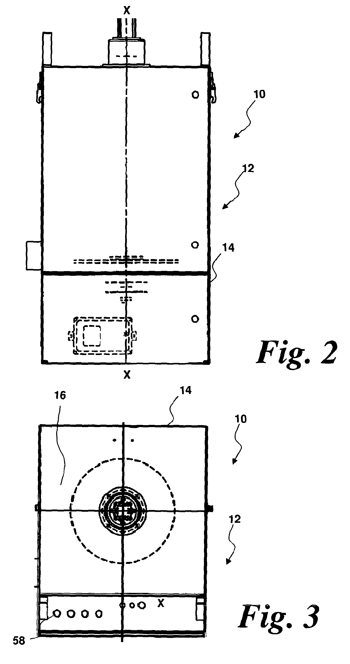
[0050]The general configuration of a filter cleaning device according to an embodiment of the present disclosure will now be described with reference to FIGS. 1 to 3. FIG. 1 shows a perspective view of a filter cleaning device 10. FIGS. 2 and 3 show orthogonal views of the filter cleaning device 10.

[0051]The filter cleaning device 10 comprises a substantially rectangular body 12 including an outer casing 14 formed from a suitable material such as aluminium or steel. An openable cover 16 is pivotably connected to the outer casing 14 at an upper end thereof and is connected to the outer casing 14 by means of hinges 16a. The cover 16 is openable to provide access to the interior of the filter cleaning device 10 for the insertion of filters for cleaning and removal of filters once cleaned.

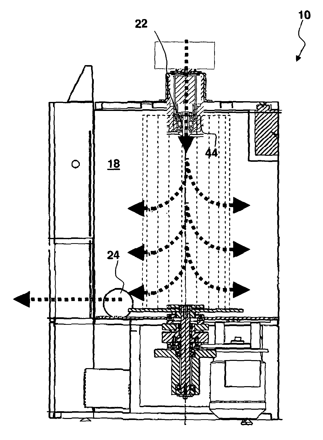
[0052]FIGS. 4 and 5 show section views through the filter device 10. In FIG. 4, the cover 16 is shown both in a closed position and in an open position. In FIG. 5, the cover 16 is shown in the closed, ...


PUM

PropertyMeasurementUnit
pressureaaaaaaaaaa
mechanical agitationaaaaaaaaaa
mechanicalaaaaaaaaaa

Abstract

A filter cleaning device includes a cleaning chamber operable to receive a gas filter to be cleaned, the cleaning chamber having an inlet through which a gas flow can be admitted and an outlet for gas flow leaving the cleaning chamber, the inlet and outlet being arranged such that the airflow is forced to pass through at least a part of the filter when inserted, the filter cleaning device further comprising a mechanical agitation arrangement operable, in one mode of operation, to generate a linear oscillation along an axis of the filter when inserted and, in another mode of operation, to rotate the filter about an axis of rotation.

Description

CROSS-REFERENCE TO RELATED APPLICATIONS[0001]This application is a 35 U.S.C. §371 national stage application of PCT / GB2012 / 052448 filed Oct. 3, 2012 and entitled “Method and Apparatus for Cleaning a Filter,” which claims priority to Great Britain Application No. GB 1117169.1 filed Oct. 5, 2011 and entitled “Method and Apparatus for Cleaning a Filter,” both of which are incorporated herein by reference in their entirety for all purposes.BACKGROUND[0002]The present disclosure relates to an air filter cleaner. More particularly, the present disclosure relates to an air filter cleaner comprising both fluid flow and mechanical vibration cleaning mechanisms.[0003]Air filters are used in a number of environments to separate dirt, dust and particulates from an incoming air flow. This is particularly important in fields such as vehicular transportation (e.g. trucks, cars and aircraft) where a clean flow of air into, for example, an internal combustion engine is required in order to ensure co...

Claims


Application Information

Patent Timeline
Patent Type & Authority Patents(United States)
IPC IPC(8): B08B5/02B08B5/04B01D46/04B01D46/00B01D41/04B01D46/52
CPCB01D46/0067B01D41/04B01D46/0073B01D46/0075B01D46/521B01D2279/60B01D46/70B01D46/78B01D46/76B01D41/00
Inventor ROYCE, JOHNCANNON, JOHNTURNER, ROGER
Owner ROYCE JOHN
Why Eureka
Try Eureka