Pile hammer

a technology of pile hammer and hammer head, which is applied in the direction of manufacturing tools, percussive tools, portable drilling machines, etc., can solve the problems of operator's being forced to reduce the pressure and thus the energy of the hammer, and the type hammer is more complex, so as to simplify the operator's job of installing and using the hammer and reduce the weight

Inactive Publication Date: 2017-02-07
TREMMIER JONATHAN +1
View PDF23 Cites 0 Cited by
  • Summary
  • Abstract
  • Description
  • Claims
  • Application Information

AI Technical Summary

Benefits of technology

[0015]Accordingly, and in accordance with a presently preferred embodiment of the present invention, an exterior cylinder is utilized to provide a one piece cylinder of uniform interior diameter and possibly an enlarged fluid reservoir about a ram and piston having a new outer diameter configuration for at least some embodiments. This construction of the preferred embodiment is believed to simplify the operator's job of installing and using the hammer. Furthermore, an exterior mode of force, whether it be steam, air, or other fluid can be provided to an inlet which directs the piston and ram upwardly possibly with a full length reservoir. At a predetermined point, internal ports of the ram communicate pressure from the ram to assist in exhausting air below the ram allowing the ram to proceed down towards a preferably improved anvil until the port is closed off which allows the air under the piston to then be compressed to start the next cycle. The improved anvil, if utilized, is hollowed out to provide a cavity rather than solid to (a) reduce weight and / or (b) provide additional air volume for upstroke energy.
[0016]Unlike the possible prior art design, the new design requires a higher predetermined minimum amount of pressure in order to begin the lifting cycle of the ram. A presently preferred embodiment requires at least 90 psi which prevents inadvertent starting as has been prone to happen with the possible prior art, but certainly abandoned, design. Round rather than prior art square reservoirs have been forced to eliminate bulging during pressurization for at least some embodiments.

Problems solved by technology

However, this type hammer is more complex and timing issues are more critical than for the single acting hammers.
Also, in hard driving, the hammers can experience upflips (the pile and thus the ram rebound too strongly) and the operator may be forced to reduce the pressure and thus the energy of the hammer.
Unfortunately, the Model 300 and / or SC3 prototypes probably do not qualify as “experimental use” even though this design has not been in use for over thirty years.
Although the tests were deemed to be successful, the impact velocity of the ram was determined to be deficient due to the positioning of the ports which tended to reduce the impact velocity of the ram.
The SC3 design was also a two-piece cylinder design having two different diameters which was difficult to assemble and run together due to the tolerances required by the construction.
Additionally, this hammer did not have a stroke control feature, and, in fact, the hammer was prone to air locking which required disassembly to reset due possibly to insufficient air reservoir space.
Another design defect included inadvertent starting, a significant safety concern which could also have been due to insufficient air reservoir space.
When the offshore market collapsed in the early 1980's with oil prices, Vulcan decided not to commercialize the product and abandoned the project.

Method used


Image

  • Pile hammer
  • Pile hammer
  • Pile hammer

Examples


Embodiment Construction

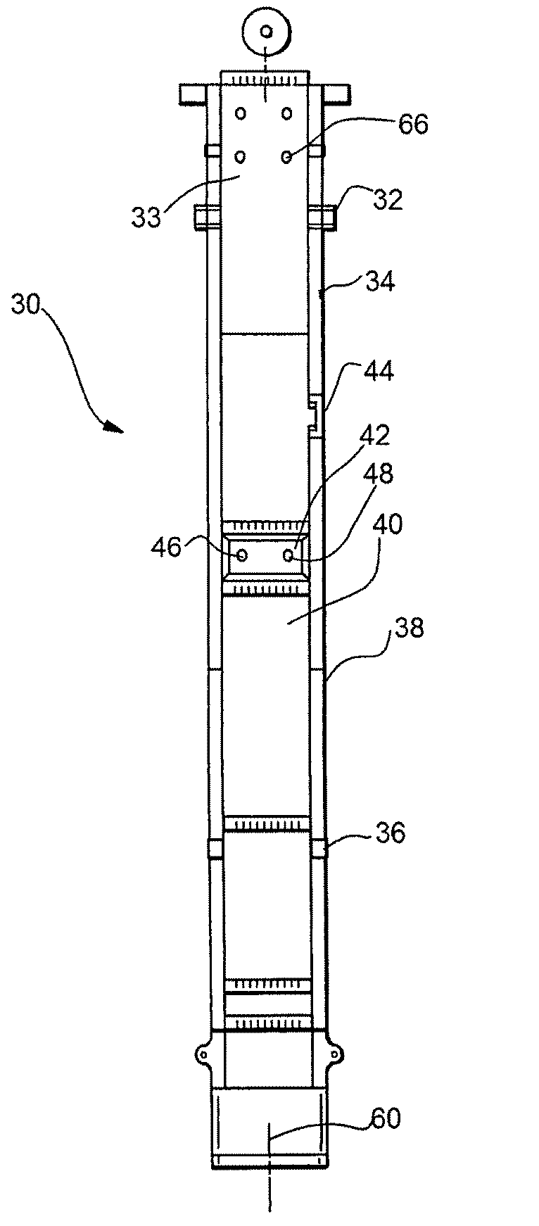
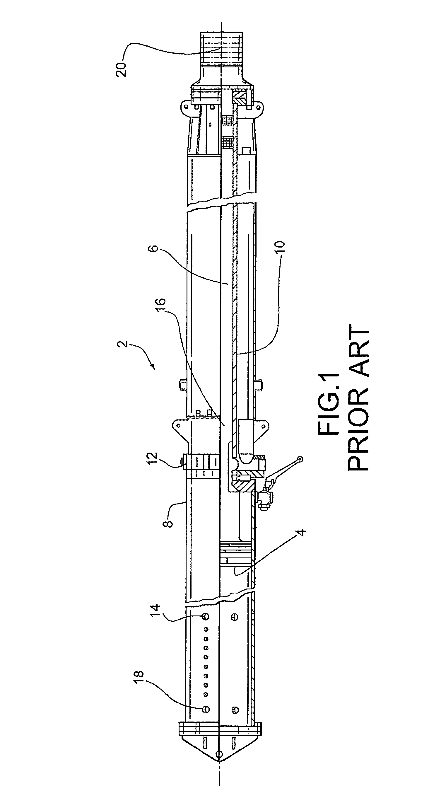
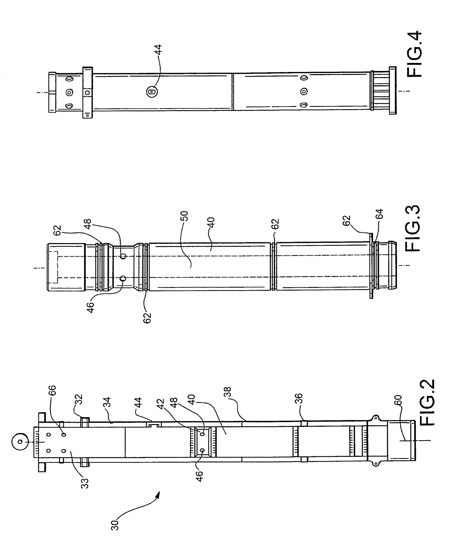
[0025]In accordance with the presently preferred embodiment of FIGS. 2-5, a pile hammer 10 is shown. Unlike the embodiment of FIG. 1 which shows a prior art hammer 2 having a separate piston 4 connected to a separate ram 6, as well as first and second cylinder diameters of cylinders 8,10 which complicate the structure, a new design is provided with an integral piston / ram and a single cylinder inner diameter. Furthermore, potentially prior art hammer 2 suffers from a number of other disadvantages, some of which were discussed above.

[0026]During operation, air or steam would be provided through inlet 12 pushing the piston upward until the piston passed the first set of vents 14 at which time the higher pressure inside the first cylinder 8 would tend to vent out of the vents 14. This displaced fluid would also be directed internal to the ram 6 through slots 16 through the upper vents 18, thus allowing the piston to coast and then start downwardly until the piston falls down past the fi...


PUM

PropertyMeasurementUnit
operating pressureaaaaaaaaaa
pressureaaaaaaaaaa
lengthaaaaaaaaaa

Abstract

An improved pile hammer provides a cylinder, such as one with a uniform interior diameter wall and uses a piston ram to cycle up and down therein to contact an anvil on a downstroke. The anvil preferably provides a cavity to both lessen the weight and improve upward force on the ram for the upstroke. An air inlet is preferably located above an air outlet which was not possible with prior art designs. An air reservoir can be located above and external to the wall in the cylinder.

Description

CLAIM OF PRIORITY[0001]This application claims the benefit of U.S. Provisional Patent Application No. 61 / 831,657 filed Jun. 6, 2013 which is incorporated herein by reference in its entirety.FIELD OF THE INVENTION[0002]The present invention relates to an improved pile hammer construction.BACKGROUND OF THE INVENTION[0003]Pile hammers have been manufactured for well over one hundred years. One early model of a very similar pile hammer is still manufactured by the company which currently manufactures and markets the hammer produced by the company which obtained that patent in the late 1800's. As one might imagine, various improvements occurred to the basic pile hammer design over the years.[0004]Many pile hammers rely on an external source of compressed air, steam, hydraulic fluid or rope release. Some hammers are single acting air / steam hammers. These are the oldest mechanically powered hammer types. A ram is moved upward by compressed air or steam in a cylinder acting against a piston...

Claims


Application Information

Patent Timeline
Patent Type & Authority Patents(United States)
IPC IPC(8): B23B45/16B25D9/00B25D11/00B25D13/00B25D16/00E21B1/00E02D7/10
CPCE02D7/10
Inventor TREMMIER, JONATHANWARRINGTON, DON
Owner TREMMIER JONATHAN
Why Eureka
Try Eureka