Windrow shield control system for a header of an agricultural harvester

a technology of control system and harvester, which is applied in the field of headers, can solve problems such as time-consuming tasks

Active Publication Date: 2017-02-14
BLUE LEAF I P INC
View PDF148 Cites 18 Cited by
  • Summary
  • Abstract
  • Description
  • Claims
  • Application Information

AI Technical Summary

Benefits of technology

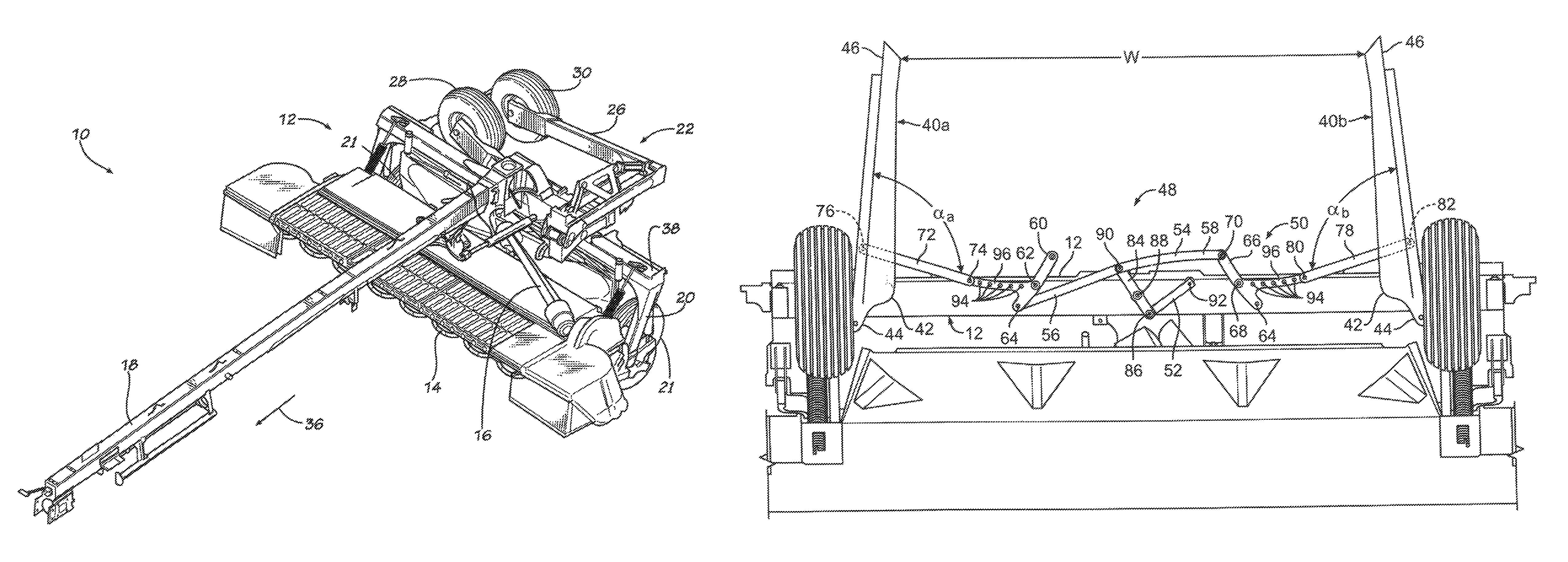
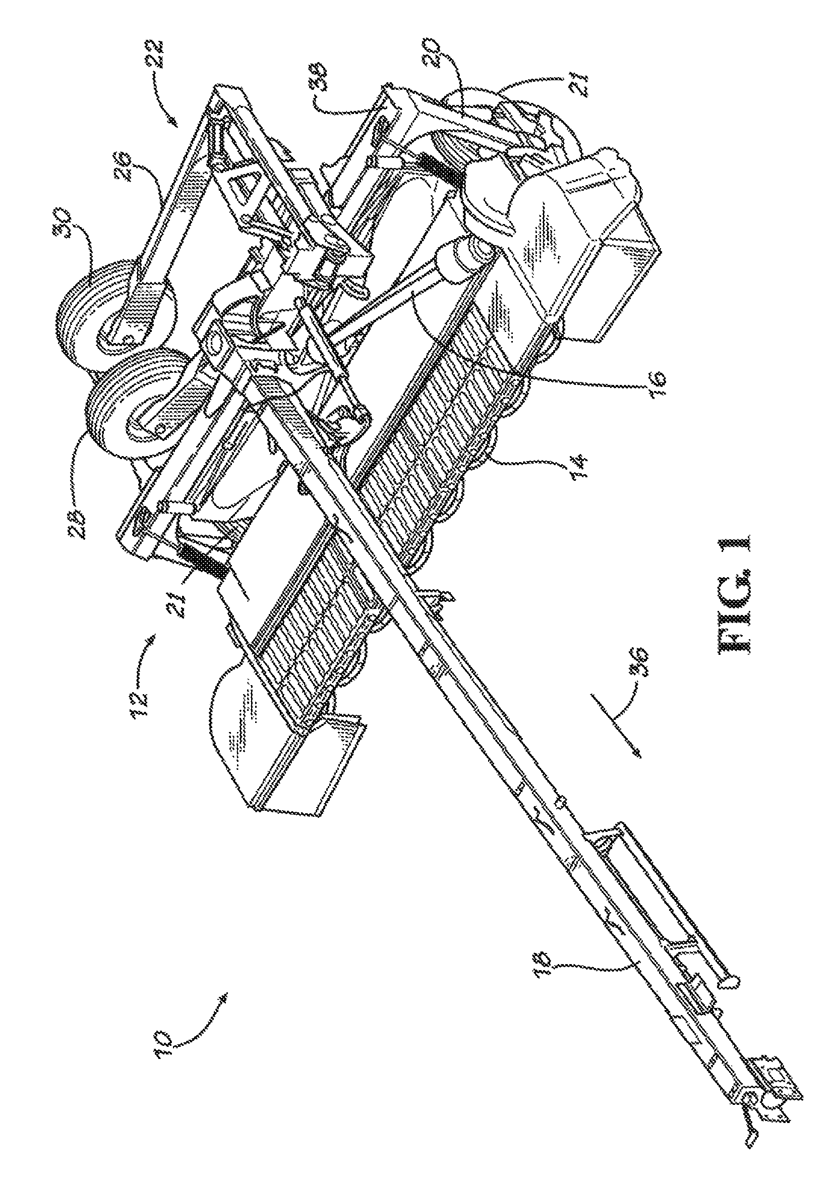
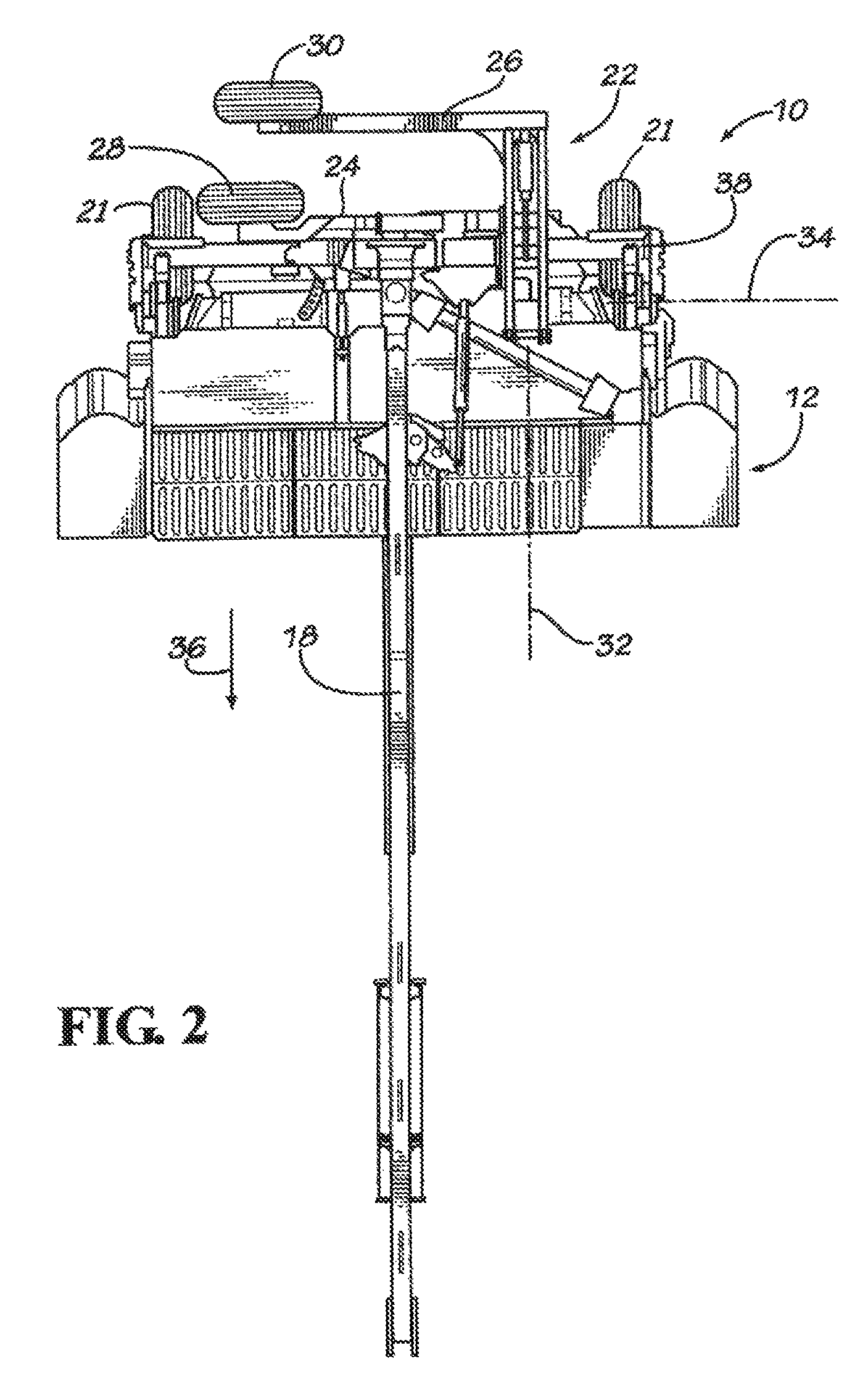
[0010]In accordance with another aspect, a windrow shield positioning adjuster including a plurality of adjustment holes is provided on elongate portions of a pair of rotating crank members which rotate roughly between 0° and 90° alignment with respect to a longitudinal direction of the header chassis. A first actuator operates a third crank member a central control arm and the first and second lateral control arms to rotate the first and second crank members. During field operation, the elongate portions of the first and second crank members are substantially aligned at approximately 0° with respect to the longitudinal direction of the chassis, e.g., perpendicular to the forward direction of travel of the mower in the field. This arrangement aligns the array of holes in the first and second crank members in such a way that the position of the windrow shields can be adjusted for narrow windrows and wide swaths, as well as the lateral positioning of the windrows. In order to transition to road / transport width, the first actuator is extended or retracted (depending on the configuration of the system) to rotate the elongate portions of first and second crank members from approximately 0° field alignment to an approximately 90° road position with respect to the longitudinal direction of the chassis. In doing so, the windrow shields are rotated or folded inward toward each other to a position relatively parallel to the longitudinal direction of the chassis. Due to the substantially small angle assumed by the first and second lateral control arms, the near parallelism of the windrow shields does not vary greatly based on the width setting of the windrow shields. That is, the windrow shields fold to a closed position which allows for the transport wheels to be deployed regardless of whether the mower has been set for wide swath formation or narrow windrow formation. This allows the first actuator to utilize its stroke to open and close the windrow shields for all windrow width settings, thereby eliminating the need for operator intervention to switch the windrow shields from field to transport positions. Thus, the first actuator simply has to be coupled to a transport wheel actuator in order to ensure that the shields are folded before the transport wheels are deployed.

Problems solved by technology

Not only is this task time consuming, the operator must remember to do so, especially in circumstances where a transport wheel frame might come into contact with the windrow shields when being disposed from its inoperative (raised) to operative (lowered) positions.
As will be appreciated, the operator may not always remember to place the windrow shields into the closed position, which can result in damage to the open windrow shields by contact of the windrow shields with the transport wheel frame when the transport wheels are lowered into their ground-engaging operative position.

Method used


Image

  • Windrow shield control system for a header of an agricultural harvester
  • Windrow shield control system for a header of an agricultural harvester
  • Windrow shield control system for a header of an agricultural harvester

Examples


Embodiment Construction

[0032]Reference will now be made in detail to the various aspects of the subject application illustrated in the accompanying drawings. Wherever possible, the same or like reference numbers will be used throughout the drawings to refer to the same or like features. It should be noted that the drawings are in simplified form and are not drawn to precise scale. In reference to the disclosure herein, for purposes of convenience and clarity only, directional terms such as top, bottom, left, right, above, below and diagonal, are used with respect to the accompanying drawings. Such directional terms used in conjunction with the following description of the drawings should not be construed to limit the scope of the subject application in any manner not explicitly set forth. Additionally, the term “a,” as used in the specification, means “at least one.” The terminology includes the words above specifically mentioned, derivatives thereof, and words of similar import.

[0033]Referring now to the...


PUM


Abstract

An agricultural harvester is provided which includes a chassis and harvesting wheels, transport wheels and windrow shields connected to the chassis. The transport wheels are deployed in concert with the windrow shields in order to avoid damage to the windrow shields during placement of the transport wheels into an operative, ground contacting position. A first actuator opens and closes the windrow shields for field and transport operations and windrow shield positioning mechanisms are configured to dispose the windrow shields in a plurality of cut crop opening widths when the windrow shields are in an open position. The first actuator is operated remotely in-cab to eliminate need for the harvester operator to dismount the harvester and open and close the windrow shields for field and road transport operations. The windrow shield positioning mechanisms may be manually adjusted or automatically adjusted in-cab.

Description

BACKGROUND[0001]The subject application relates generally to a header for use with agricultural harvesters. In particular, the subject application relates to an improved windrow shield control system for use with pull-type or self-propelled mower headers.[0002]Mower headers have been used to cut plants including, but not limited to, hay, grasses, small grains and the like for many years. Because of their particular cutting devices, such mower headers are often referred to as Disc Mower Conditioners (DMCs). A pull-type DMC is pulled by a tractor and can have a trailing tongue that pivots and is attached to the left side of the header trail frame or chassis (Side Pull DMC) or it can have a trailing tongue that pivots and attaches to the center of the header trail frame or chassis (Center Pivot DMC). Side pull DMC's can only pivot to the right of the tractor and center pivot DMC's can pivot to the left or right of the tractor. The cutting of the DMC, whether pull-type or self-propelled...

Claims


Application Information

Patent Timeline
Patent Type & Authority Patents(United States)
IPC IPC(8): A01D43/06A01D57/28
CPCA01D43/06A01D57/28
Inventor FAY, II, JEFFREY B.DESHPANDE, NAKUL VILAS
Owner BLUE LEAF I P INC
Why Eureka
Try Eureka