
Wireless communication apparatus and wireless communication system

a wireless communication and wireless communication technology, applied in the field of time synchronization utilizing wireless communication, can solve the problems of not always appropriate to utilize the average value of the time stamp contained in the beacon packet, difficulty in maintaining time synchronization among the plurality of stas connected to the ap, and uneven degree of the effect of the time stamp from each ap on the target tim

Active Publication Date: 2017-02-14
KK TOSHIBA
View PDF10 Cites 1 Cited by
  • Summary
  • Abstract
  • Description
  • Claims
  • Application Information

AI Technical Summary

Benefits of technology

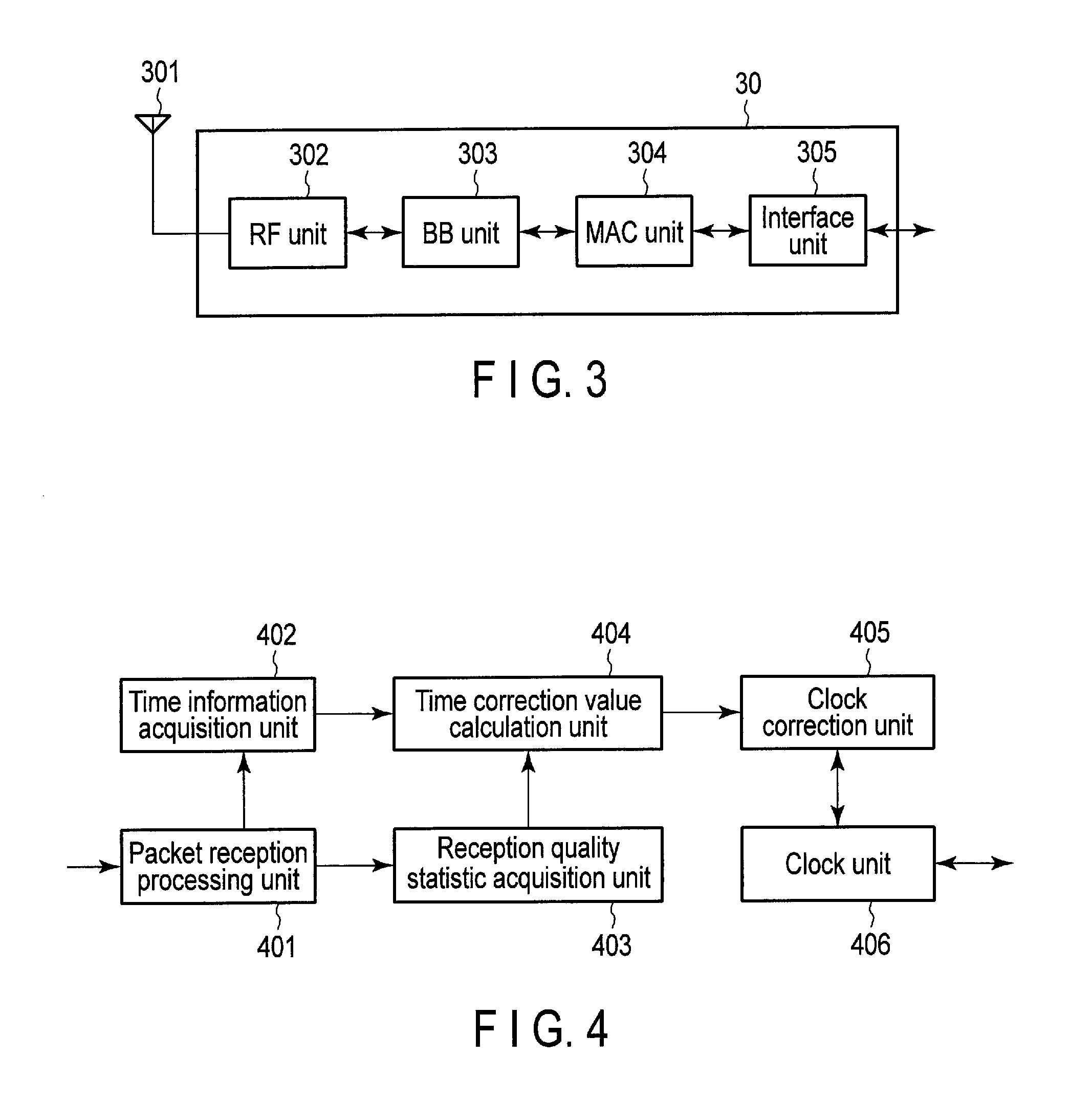
The patent text describes a wireless communication system that uses time synchronization to ensure that multiple devices connected to an access point are aware of the same time. However, this can be difficult to achieve if the access point fails or if there are multiple APs transmitting beacon packets. The patent proposes a solution to this problem by using a MAC unit to calculate a time correction value based on the statistic of reception quality and the time weight of the second time information contained in the beacon packet. This value is used to adjust the first time information and ensure that the multiple devices connected to the access point are synchronized with the same time.

Problems solved by technology

However, according to such a synchronization technique, if a failure occurs in the AP or if the beacon packet from the AP fails to be received due to, for example, a variation in wireless propagation path, maintaining the time synchronization among the plurality of STAs connected to the AP is difficult.
However, it is not always appropriate to utilize the average value of the time stamps contained in the beacon packets from the plurality of APs, as a target time for time synchronization.
First, as described above, different APs generally measure different absolute times, and thus, the absolute value of the time stamp may vary among the plurality of APs. That is, the degree of the effect of the time stamp from each AP on the target time is not uniform.
Second, links among the plurality of APs and the plurality of STAs are not necessarily stable. It may be difficult for a certain STA to stably receive beacon packets from a certain AP.

Method used


Image

  • Wireless communication apparatus and wireless communication system
  • Wireless communication apparatus and wireless communication system
  • Wireless communication apparatus and wireless communication system

Examples


first embodiment

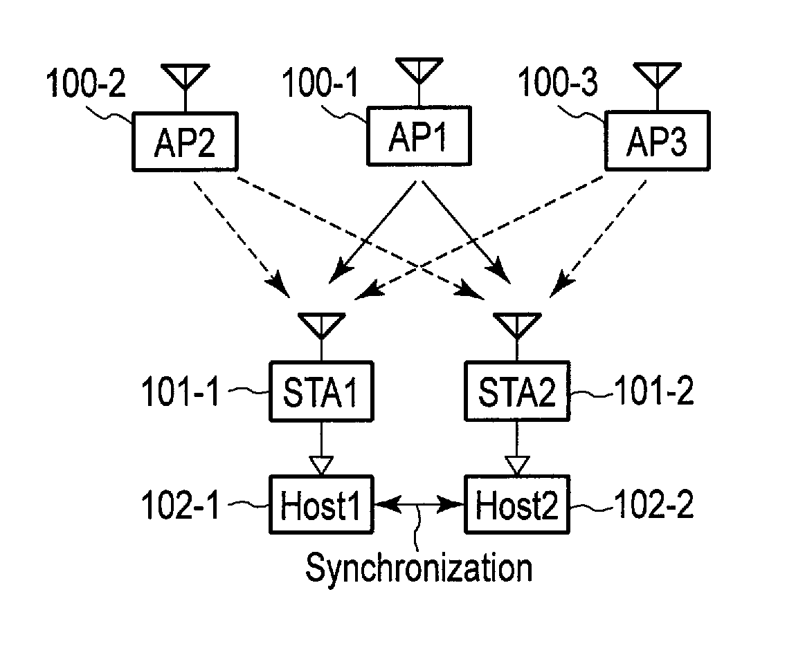
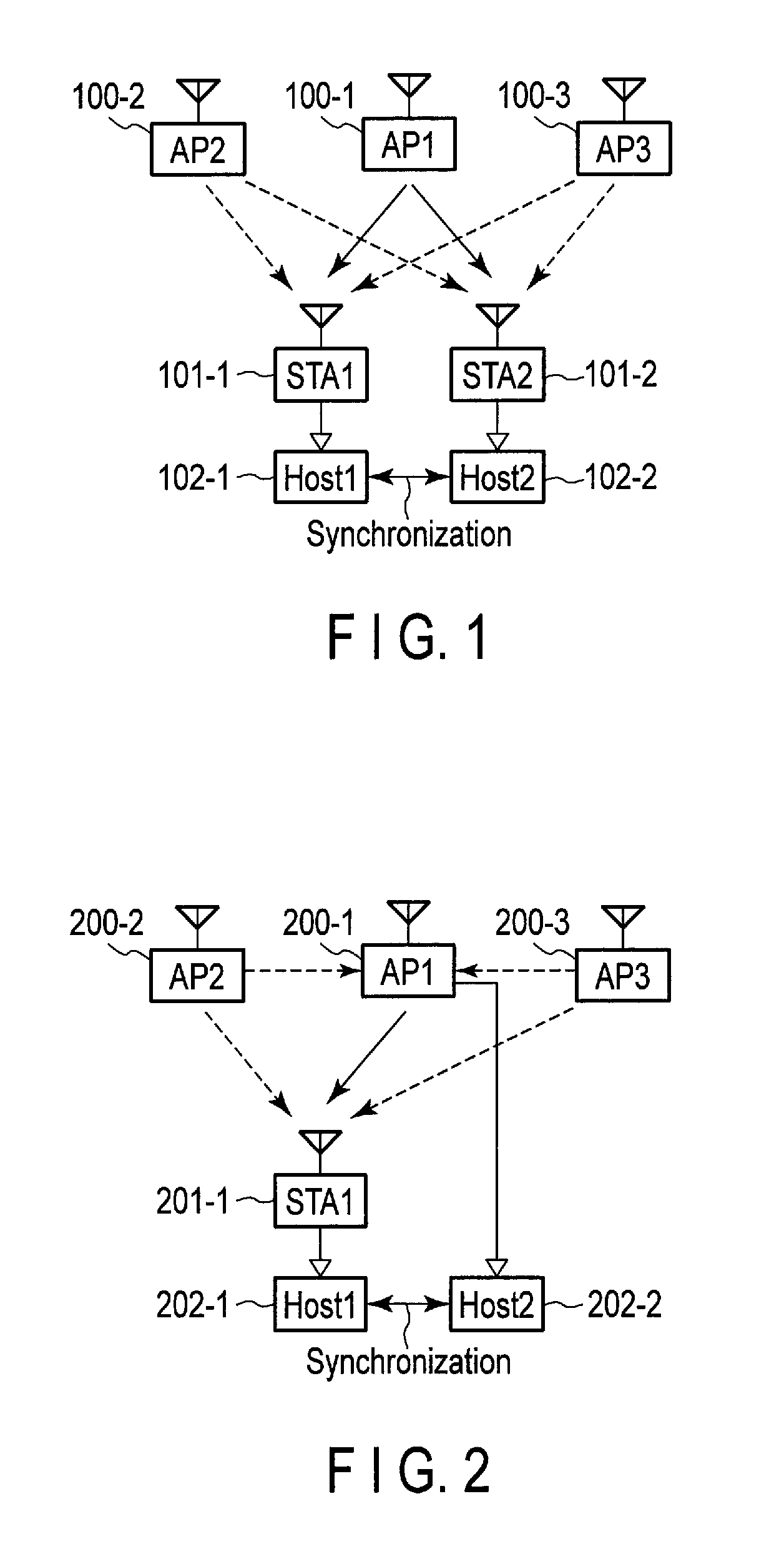
[0026]A wireless communication apparatus according to a first embodiment forms, for example, a wireless communication system shown in FIG. 1. The wireless communication system in FIG. 1 is based on an infrastructure mode for a wireless LAN. The wireless communication system inFIG. 1 includes an STA 101-1 and an STA 101-2 which are connected to an AP 100-1. Moreover, in the wireless communication system in FIG. 1, an AP 100-2 and an AP 100-3 are arranged around the STA 101-1 and the STA 101-2. In FIG. 1, the STA 101-1 and the STA 101-2 correspond to wireless communication apparatuses according to the first embodiment.

[0027]In a common wireless LAN system, a given STA matches time information from a clock inside the STA with a time stamp contained in a beacon packet from an AP to which the STA is connected. As a result, time synchronization is achieved between the STA and the AP to which the STA is connected and further among a plurality of STAs connected to the AP.

[0028]The STA 101-1...

second embodiment

[0098]The wireless communication apparatus according to the first embodiment basically allows beacon packets from all surrounding APs to be utilized for time synchronization. Such an operation enables stable time synchronization, but may increase processing loads more than necessary particularly when a large number of APs are operating around.

[0099]Thus, a wireless communication apparatus according to a second embodiment selects, in an autonomous distributed manner, any of surrounding APs that has high link stability, and utilizes only beacon packets from the selected AP for time synchronization. Such an operation is expected to suppress processing loads, stabilize time synchronization, and improve accuracy.

[0100]A MAC unit of the wireless communication apparatus according to the second embodiment is illustrated in FIG. 8. The MAC unit in FIG. 8 is different from the MAC unit in FIG. 4 in that the MAC unit 8 comprises an AP selection unit 807. FIG. 8 shows a packet reception process...

third embodiment

[0106]The wireless communication apparatus (corresponding to an STA) according to the second embodiment selects, in an autonomous distributed manner, any of the surrounding APs that has high link stability, and utilizes only beacon packets from the selected AP for time synchronization. Such an operation is expected to suppress processing loads and to improve the stability and accuracy of time synchronization. However, the second embodiment does not necessarily utilize the same AP for time synchronization among a plurality of STAs.

[0107]On the other hand, a wireless communication apparatus (corresponding to an AP) according to a third embodiment selects, in a centralized control manner, an AP for time synchronization among a plurality of STAs connected to the AP (that is, the STAs having the same SSID as the SSID of the AP) based on reception quality information or reception quality statistics transmitted by the plurality of STAs. Such an operation is expected to suppress processing ...


PUM


Abstract

According to an embodiment, a wireless communication unit includes a media access control (MAC) unit. The MAC unit includes a clock unit, an acquisition unit and a calculation unit. The clock unit includes a register which stores periodically counted-up first time information. The acquisition unit acquires a statistic for reception quality information on the received packet. The calculation unit normalizes the second time information, weights the normalized second time information using a time weight based on the statistic, and calculates a time correction value for correcting the first time information, using the weighted and normalized second time information. The time weight increases with increasing link stability indicated by the statistic.

Description

CROSS-REFERENCE TO RELATED APPLICATIONS[0001]This application is based upon and claims the benefit of priority from Japanese Patent Application No. 2013-130386, filed Jun. 21, 2013, the entire contents of which are incorporated herein by reference.FIELD[0002]Embodiments relate to time synchronization utilizing wireless communication.BACKGROUND[0003]In a wireless LAN (Local Area Network), an AP (Access Point) transmits a beacon packet containing time information (hereinafter referred to as a time stamp) from a clock inside the AP. Then, an STA (STAtion) connected to the AP (that is, the STA having the same SSID (Service Set ID) as the SSID of the AP) receives the beacon packet and matches the time information from the clock inside the STA with the time stamp contained in the received beacon packet. As a result, time synchronization is achieved among a plurality of STAs connected to the same AP.[0004]However, according to such a synchronization technique, if a failure occurs in the AP...

Claims


Application Information

Patent Timeline
IPC IPC(8): H04J3/06
CPCH04J3/0664H04J3/0641
Inventor TOHZAKA, YUJIKUDO, HIROKISAKAMOTO, TAKAFUMI
Owner KK TOSHIBA
Learn More